Welcome to Laser Pointer Forums - discuss green laser pointers, blue laser pointers, and all types of lasers

LPF Donation via Stripe | LPF Donation - Other Methods

Links below open in new window

ArcticMyst Security by Avery

Please help! :)


Rachel

0
Joined
Dec 20, 2016
Messages
50
Points
0
Rachel---HAve you look at DTR's 08 diode page?
As you scroll down, it shows many output level as a function of amp and voltage the diode is capable of---see: https://sites.google.com/site/dtrlpf/home/diodes/nubm08-455nm-4-3w-laser-diode
N's data sheet is available on that page also.

Ah thanks for this, this is useful!

Can I ask why he doesn't increase the voltage tho?

With the new battery I will be using (11.1V) it's 3.5V drop out voltage for the regulator = 7.6 minus heat maybe 0.6V = 7V

7V is well over the 4.8V he uses. He uses that because it's the max rating for the voltage on the data sheet of the laser...

Just don't want to blow mine! They cost quite a lot and I've put a lot of time into model!
 

Encap

0
Joined
May 14, 2011
Messages
6,125
Points
113
Ah thanks for this, this is useful!

Can I ask why he doesn't increase the voltage tho?

With the new battery I will be using (11.1V) it's 3.5V drop out voltage for the regulator = 7.6 minus heat maybe 0.6V = 7V

7V is well over the 4.8V he uses. He uses that because it's the max rating for the voltage on the data sheet of the laser...

Just don't want to blow mine! They cost quite a lot and I've put a lot of time into model!

Look at page 2 of the diode data sheet here: https://drive.google.com/file/d/0B_6-KC5wFXIJa3Bxak83N0xaa2s/view?usp=sharing
It says min operating voltage 3.6----maximum operating voltage 4.8.

DTR shows a wide range of outputs from min voltage and amps to maximum voltage and amps---DTR runs it at 4.8 and pushes it raising the amps until the output start to fall off/ decrease--to show what the diode is capable of when pushed.

If the output of your driver to the diode is 7V that is way over 4.8 and not necessary even if the diode can withstand that and it may not be able to. maximum diode output DTR shows is 6.792W at 5.0 amps 4.7 volts.
Pretty good for a diode that is supposd to be a 4.3W output diode.
 
Last edited:

Rachel

0
Joined
Dec 20, 2016
Messages
50
Points
0
Look at page 2 of the diode data sheet here: https://drive.google.com/file/d/0B_6-KC5wFXIJa3Bxak83N0xaa2s/view?usp=sharing
It says min operating voltage 3.6----maximum operating voltage 4.8.

DTR shows a wide range of outputs from min voltage and amps to maximum voltage and amps---DTR runs it at 4.8 and pushes it raising the amps until the output start to fall off/ decrease--to show what the diode is capable of when pushed.

If the output of your driver to the diode is 7V that is way over 4.8 and not necessary even if the diode can withstand that and it may not be able to. maximum diode output DTR shows is 6.792W at 5.0 amps 4.7 volts.
Pretty good for a diode that is supposd to be a 4.3W output diode.


Yea thanks encap I know the data sheet as I've pretty much studied it ha.
I'll see what cyparagon has to say about the above rated voltage he seems to know quite a lot about the very technical bits

Rach
 

Encap

0
Joined
May 14, 2011
Messages
6,125
Points
113
Yea thanks encap I know the data sheet as I've pretty much studied it ha.
I'll see what cyparagon has to say about the above rated voltage he seems to know quite a lot about the very technical bits

Rach

Don't know if either of these will help you but have a look and see:

https://sites.google.com/site/dtrlpf/home/flexdrives/rog8811

and

see: http://laserpointerforums.com/f44/running-multiple-lser-diodes-nubm08-99263-2.html
especially post #23

If anyone can help you cyparagon can or you can always PM styropyro who did it already successfully.

PS did you make or do you have a dummy load to test the voltage and mAs to the LDs? If not make one --better than to risk expensive diodes
 
Last edited:
Joined
Sep 12, 2007
Messages
9,399
Points
113
Can I ask why he doesn't increase the voltage tho?

Firstly, the voltage IS increasing. The power supply in frame is too low resolution, but if there were more digits, you would see them increment as the current increases.

Surely you're familiar with constant voltage regulation. You hold the voltage constant, and the load takes whatever current it needs, provided the current is within certain design parameters. Constant current regulation is the opposite. You hold the current constant, and the load takes whatever voltage it needs, provided the voltage is within certain design parameters. You CANNOT control both simultaneously.

With the new battery I will be using (11.1V) it's 3.5V drop out voltage for the regulator = 7.6 minus heat maybe 0.6V = 7V

That is NOT how a regulator works. A regulator (constant current linear in this case) holds current constant, 3.5V is the MINIMUM dropout voltage. the actual voltage dropped by the regulator will be the difference between the supply voltage and the load voltage.

You hold the current constant (1.3A or whatever), provided the voltage is within certain design parameters. The design parameter depends on the voltage input in this case: Input voltage -3.5V is the maximum voltage for the load. As long as the load is between 0V and 7.6V, the current will be held at 1.3A. Any voltage difference between the load and the supply will be burned away as heat.
 

Rachel

0
Joined
Dec 20, 2016
Messages
50
Points
0
Thanks for your help encap; the link was very useful.

And okay that's good then, someone's already done it and yea I could do. Is he still active ?
 

Rachel

0
Joined
Dec 20, 2016
Messages
50
Points
0
Thanks for the help cyparagon, for some reason it won't let me quote you!..
there's a lot of valued information there that I've thought of doing like using the voltage regulator and the current regulator working together and if you can use them both in the circuit, but as Uve just told me you can't, so thanks for that.

I understand that the way LD are so they need a current regulator bcuase they are gready. And you're telling me that any excess voltage that is not needed the by the LD will be rejected in heat form? So if the maximum voltage for the laser is rated at 4.8V minus the minimum 3.5V will give us 7.6V left and so 7.6V - 4.8V = 2.8V will be rejected as heat? So it's okay to run the laser above its recommended voltage ranges?

Thanks :)
 
Joined
Sep 12, 2007
Messages
9,399
Points
113
I understand that the way LD are so they need a current regulator bcuase they are gready.

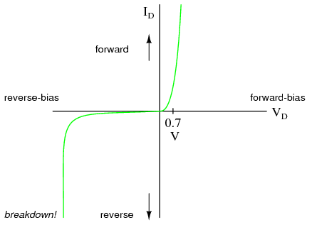
No, it is because they are diodes. Look at the curve of a standard diode

03253.png


While you could conceivably regulate voltage instead, there is a LARGE change in current for a minuscule change in voltage. It is even worse than that, because the exact curve is different from device to device, and from temperature to temperature.

A laser diode curve is the same shape, but instead of that cliff being 0.7V, it's a few volts. Driving a diode at 4.6V might conduct 200mA for one diode, but 2A for another. Or 4V into a diode at room temperature might be 300mA while the SAME diode at the SAME voltage but 20C warmer might conduct 600mA. It is too easy to "fall off the cliff" and destroy the diode with over-current, to drive them in voltage regulation.

And you're telling me that any excess voltage that is not needed the by the LD will be rejected in heat form?

By the regulator, yes.

So it's okay to run the laser above its recommended voltage ranges?

I know it's hard, but you need to shake this idea of voltage regulation. We regulate current. You are driving a CURRENT through the device, and the voltage will settle at whatever the forward voltage is for that scenario.
 

Rachel

0
Joined
Dec 20, 2016
Messages
50
Points
0
No, it is because they are diodes. Look at the curve of a standard diode

03253.png


While you could conceivably regulate voltage instead, there is a LARGE change in current for a minuscule change in voltage. It is even worse than that, because the exact curve is different from device to device, and from temperature to temperature.

A laser diode curve is the same shape, but instead of that cliff being 0.7V, it's a few volts. Driving a diode at 4.6V might conduct 200mA for one diode, but 2A for another. Or 4V into a diode at room temperature might be 300mA while the SAME diode at the SAME voltage but 20C warmer might conduct 600mA. It is too easy to "fall off the cliff" and destroy the diode with over-current, to drive them in voltage regulation.


I know it's hard, but you need to shake this idea of voltage regulation. We regulate current. You are driving a CURRENT through the device, and the voltage will settle at whatever the forward voltage is for that scenario.


Thanks for the knowledge on this, it was very interesting :)
I didn't intend on wiring it in a voltage regulation form as I know diodes are greedy with current and will take as much as they can and blow themselves.


I didn't intend to use my circuit as voltage regulation so sorry if I came across wrongly :D

And thanks for telling me that the excess voltage will not be used and will just be turned away as a heat loss as I was worried that the laser would consume too much voltage and I'd blow them

thanks
 
Last edited:

Rachel

0
Joined
Dec 20, 2016
Messages
50
Points
0
Also a question about the lm317's in my circuit ... Because I wired them up slightly wrong and the current was regulated by the lm317 current and not the resistor ... do you thinks it's best I bought new lm317's? Or do you think they will be okay and not damaged?

Thank you

Rach.
 

Rachel

0
Joined
Dec 20, 2016
Messages
50
Points
0
Could u please help with my previous questions pleeease! It will be my last :p xxx
 

diachi

0
Joined
Feb 22, 2008
Messages
9,700
Points
113
Could u please help with my previous questions pleeease! It will be my last :p xxx


Test them with a test load to make sure they are working and set correctly before hooking them up to your LDs? That's best practice anyway.
 

Rachel

0
Joined
Dec 20, 2016
Messages
50
Points
0
Test them with a test load to make sure they are working and set correctly before hooking them up to your LDs? That's best practice anyway.

Thanks Diachi :)

What do you usually use for your test load ?

Thanks x !
 

diachi

0
Joined
Feb 22, 2008
Messages
9,700
Points
113
Thanks Diachi :)

What do you usually use for your test load ?

Thanks x !


You can make one from rectifier diodes (number depends on required output voltage) and a resistor, although I've seen ready built loads for sale on here.

Use the search bar at the bottom of the page. :)
 

Encap

0
Joined
May 14, 2011
Messages
6,125
Points
113
Thanks Diachi :)

What do you usually use for your test load ?

Thanks x !

Here are a few---

http://laserpointerforums.com/f67/test-dummy-load-share-69519.html

http://laserpointerforums.com/f51/how-make-selectable-dummy-load-very-depth-64585.html

There is also a diagram and instruction for a dmmy load in the first link in my post #37 if you scroll down last section it is there--apparently you did not look at that link.

Really, you should use the search function and see what is available first as diachi indicated---you can't expect people to spoon feed you information that is easily available and within the lpf search data base, forever----doing so gets old very quickly.

If it doesn't matter enough to you to search and find the information---why should it matter to anyone else--especially on a repeated basis?
 
Last edited:


Top