Welcome to Laser Pointer Forums - discuss green laser pointers, blue laser pointers, and all types of lasers

Buy Site Supporter Role (remove some ads) | LPF Donations

Links below open in new window

FrozenGate by Avery

Nugm02 circuit resistance

There is no magic or "better than anyone else" type of laser driver. U gotta just understand basic science behind what you are looking for and find a driver that suits your needs

Yo on that note @Giannis_TDM, do you think I could use an ATX PSU's PCI-E output to drive a 12v laser array? Those things are cheap as hell and (if their advertising is to be believed) should have low ripple
No, The voltage ripple although part of the equation is not as important as the current ripple, also AFAIK PC power supplies are actually not that good performers in terms of ripple since that 12 is getting stepped down by other local regulators on the components themselves. In short, I would say no, have at least an LM338 to regulate current, also what array did you find that runs at 12?


No, The voltage ripple although part of the equation is not as important as the current ripple, also AFAIK PC power supplies are actually not that good performers in terms of ripple since that 12 is getting stepped down by other local regulators on the components themselves. In short, I would say no, have at least an LM338 to regulate current, also what array did you find that runs at 12?
No diode runs at 12V, but my thinking was stringing several in series. But yeah I see what you mean, best bet is to stick with DIY inefficient IC-based regulators with massive heatsinks or to buy a proper expensive/efficient driver
 
No diode runs at 12V, but my thinking was stringing several in series. But yeah I see what you mean, best bet is to stick with DIY inefficient IC-based regulators with massive heatsinks or to buy a proper expensive/efficient driver
Who talked about diodes? both you and I said arrays. Also, the 40w red engineering sample array I have actually does run at 12.6v, I use one of my drivers per string set to 1.7A , theoretically, I could only use 1 per 2 strings with a 1.5A per string setting but that is just calling out for unbalanced current across the strings due to the vF per diode being different at x current.
 
Who talked about diodes? both you and I said arrays. Also, the 40w red engineering sample array I have actually does run at 12.6v, I use one of my drivers per string set to 1.7A , theoretically, I could only use 1 per 2 strings with a 1.5A per string setting but that is just calling out for unbalanced current across the strings due to the vF per diode being different at x current.
Makes sense, and sorry that I keep exploiting you for your electrical knowledge lol :)

Just out of curiosity again, if I were to make a super compact laser using a small driver and a cheap ass button. Is it possible to both add efficient reverse polarity protection as well as indirect switching (I want the mosfet to handle the current) all using just 1 P-Channel mosfet? I assume that one would need 2 mosfets to accomplish this right?
Who said you're exploiting me? I, by my own will, answer the questions, So you can technically do it with one fet but it gets tricky, if you don't do it right I.E don't have a pull up resistor the gate charge will keep the fet semi-open allowing reverse pol to run through.
 
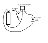
View attachment 73935
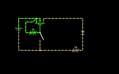
So something like this!
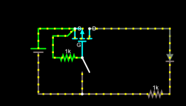
I tested out a few circuits including the one you suggested but sadly found that the only one that preserves that "indirect switching" attribute is this one:
I don't think you can pull it (lossless reverse polarity protection+indirect switch) off with one mosfet
1640778528617.png

I will invest in some circuit drawing software at some point in the future don't worry XD
 
I tested out a few circuits including the one you suggested but sadly found that the only one that preserves that "indirect switching" attribute is this one:
I don't think you can pull it (lossless reverse polarity protection+indirect switch) off with one mosfet
View attachment 73937

I will invest in some circuit drawing software at some point in the future don't worry XD
The software I used was an online simulator named falstad, you sure your tests were ok? cause it worked flawlessly in the sim, observe that the gate and source are flipped. (due to the body diode)
 
Is that 1k resistor right after the diode important or does it just represent the load? I only added in the resistor in parallel with the gate. My mosfet did not even allow any current to pass in the above configuration, but when I flipped the battery it always allowed current to pass regardless of switch.

Here are the specific mosfets I have:
 
Wait I dumb and mixed up battery +- notation. Yes the above battery orientation worked, but it always allowed full current regardless of switch
 
Wait I dumb and mixed up battery +- notation. Yes the above battery orientation worked, but it always allowed full current regardless of switch
Are you sure you have wired source to the battery and drain to the load?
 
Ok turns out sim assumes ideal components, got you a tested circuit that works IRL, (Used a P40NF10L p channel fet for the test, the funny thing is that this circuit also has a slow power-off effect), making some more measurements and the schematic rn

Scrap that, did the aforementioned tests and as I feared, the gate in the circuit I built is driven in its linear zone aka the fet is not fully on... In conclusion yes, you need 2 fets
 
Last edited:
Ok turns out sim assumes ideal components, got you a tested circuit that works IRL, (Used a P40NF10L p channel fet for the test, the funny thing is that this circuit also has a slow power-off effect), making some more measurements and the schematic rn

Scrap that, did the aforementioned tests and as I feared, the gate in the circuit I built is driven in its linear zone aka the fet is not fully on... In conclusion yes, you need 2 fets
Yeah, from my understanding it might have worked with an enhancement mode mosfet
 
Who talked about diodes? both you and I said arrays. Also, the 40w red engineering sample array I have actually does run at 12.6v, I use one of my drivers per string set to 1.7A , theoretically, I could only use 1 per 2 strings with a 1.5A per string setting but that is just calling out for unbalanced current across the strings due to the vF per diode being different at x current.
Do you have a picture of the 40w red ?


Back
Top