Welcome to Laser Pointer Forums - discuss green laser pointers, blue laser pointers, and all types of lasers

Buy Site Supporter Role (remove some ads) | LPF Donations

Links below open in new window

FrozenGate by Avery

NUBM37 Combination through PBS?

GaussianFun

New member
Joined
Sep 4, 2023
Messages
4
Points
3
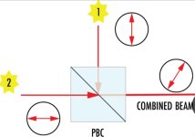
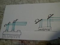
Hello all. New to the forum. Looking at doing a new setup with two NUBM37 Diode arrays. Ive seen a few on youtube and as far as ive found nobody has combined 2 of them before. I was wondering if it would be possible to run 2 through a 1" PBS (PBS251 from Thorlabs) without melting the cube? The specs on the PBS251 show it having the capacity to handle 350W/cm^2 continous wave. This should allow it to run ~240W from the Two modules without completely frying the cube correct? And will the homogenized beam should be a combined output of the both? I would not expect more than a 4% loss of power through the cube due to efficiency losses though that theory needs testing.

This will be done with safe tasting and 400-500NM OD7+ glasses of course.
 

Attachments

  • 20230831_222126.jpg
    20230831_222126.jpg
    101.3 KB · Views: 7


Great thread, thanks for linking. have there been any other better developments combining the beams since then / a more optimal setup with a better power output?
 
You can knife edge each row of 7 emitters from nubm35's so that you have a better field of beams that better overlap at your max distance.
What are you trying to do ? Work up close or at a distance ?
 
Last edited:
You can knife edge each row of 7 emitters so that you have a better field of beams that better overlap at your max distance.
What are you trying to do ? Work up close or at a distance ?
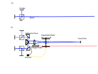
My goal is to make a adjustable focal point from 25 meters - 1000 meters that should have a forgivable footprint on target at around 1 square inch so energy transmission is consistent . I would like to start by combining two NUBM37's then move on to four NUBM37's as illustrated. If possible it would be cool to incorporate an Arduino and a separate laser range finder that can auto-adjust telescope lengths for beam convergence/ divergence by use of a position sensor for the lenses on motors.

Ideally the input from the range finder will allow the computer to tell the optics to move X distance on a track .
 

Attachments

  • NUBM27000.png
    NUBM27000.png
    26.4 KB · Views: 10
Last edited:
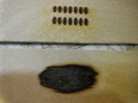
The fast axis divergence of each beam is very aggressive so your beams turn into long bars over distance and the alignment of those arrays is only designed for short distance ( the bars spread out over distance ), apparently you haven't examined the output of one of these over any distance, it doesn't take far, 10 meters and you will see what's going on.

Point is you can't lens those arrays to do work/burn for very far, I have used a expedited beam expander to get a burning cluster at 15 feet that was about 18x20mm, but don't expect to do any work/burning at much longer distances without correcting each beam and then knife edging them all, but even then you can't expect anything even close to 1000 meters or even 100 meters of useful working range from these, they just don't have the necessary beam quality or the coherence length.

SANY6795.JPG
 
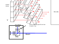
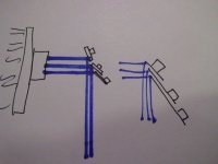
So the main issue being fast axis beam divergence should need a solution- a spaced out array of anamorphic lens with a cylindrical design could work. OR a stacked row of triangle cut anamorphic lens pairs. each row would travel through the lens and correct the beams. For the 24 Diodes in a NUBM37 , there would be 4 Sets of lens pairs for elliptical emission/correction. Then it could pass through a PBS and whatever optic/ beam expander or telescope setup since the beams would be corrected. ... It looks like Optocity linked here: "http ://www. optocity.com/pris m-anamorphic.htm "(remove the spaces, still a newbie!) can do custom cut anamorphic lens at specified dimensions. The lens would be cut to be rectangular profiled like a 25mm x 5mm instead of their basic 5mm x 5mm options.

might be a strong possibility of working it seems. as the saying goes got to make do with what you have.

Just spit balling ideas here. I Don't know everything optics and laser- but have a pretty good grasp of digital electronics.
 

Attachments

  • V1.png
    V1.png
    79.6 KB · Views: 12
I don't know everything about anything, but I enjoy learning as much about most everything that I can.

It would be better to correct each beam individually but you could try to do it in rows..... however it's the short side of the beams spot that becomes very wide over just a few meters.

So in the case of the nubm35 which has 2 rows of 7 you would need 7 prism pairs, nubm37 either 4 or 6 depending on the layout, but misalignment will become an issue.

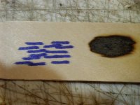
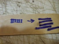
You see what starts as a tall vertical rectangle becomes a wider horizontal rectangle, so you have 2 bundles from the 2 rows of 7 that sort of overlap ( nubm35 ), but with distance, just a few meters, the spread ( width ) of the bundles also expands. The factory alignment looks good up close, but with any real distance you see it's far from perfect.

You really need to build your own array from individual diodes and use a cylindrical pair to correct each beam, then knife edge all the beams and finally run those beam bundles through a big beam expander.

I played with multiple beam concepts a while back here > Multiple Beams

Anyway you can get a nubm35 and safely test it and see what I am talking about, it's pretty neat they do as well as they do using a tiny reflector to align each beam inside the array.


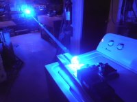
This is from 8 inches away to 8 feet away and the length of the bars continue to grow as does the misalignment of the bars with distance.

SANY7113.JPG

SANY7116.JPGSANY7117.JPG

You could knife edge each string of 7 from several arrays into a bundle aligned to infinity and run that bundle through a big beam expander, or try to correct by way of the prism pairs, also you can easily remove the gang lens and replace it with one of your own gang lenses or lens arrays with lenses of a different focal length to aid in correcting the beams as per having space to work, the substrate stacks are sealed behind an AR coated window, the gang lens is only held in place with a couple beads of glue over top of the arrays window.
Although improvement is possible, these will never be able to produce a 1 inch spot @ 1000 meters, but they could be bundled and improved a little to make for more fun a little further out. ** Always Remember Safety 1st **
Note: nubm35's are the better deal and can be had for less $$$ per unit, also could be easier to work with.
SANY6866.JPG
SANY7124.JPG
SANY7122.JPG
 
Last edited:


Back
Top