Welcome to Laser Pointer Forums - discuss green laser pointers, blue laser pointers, and all types of lasers

LPF Donation via Stripe | LPF Donation - Other Methods

Links below open in new window

ArcticMyst Security by Avery

NUBM08 Array - sources for knife edge reflectors, fiber coupling strategies?

Joined
Sep 20, 2016
Messages
8
Points
0
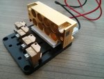
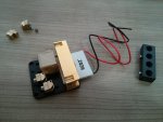
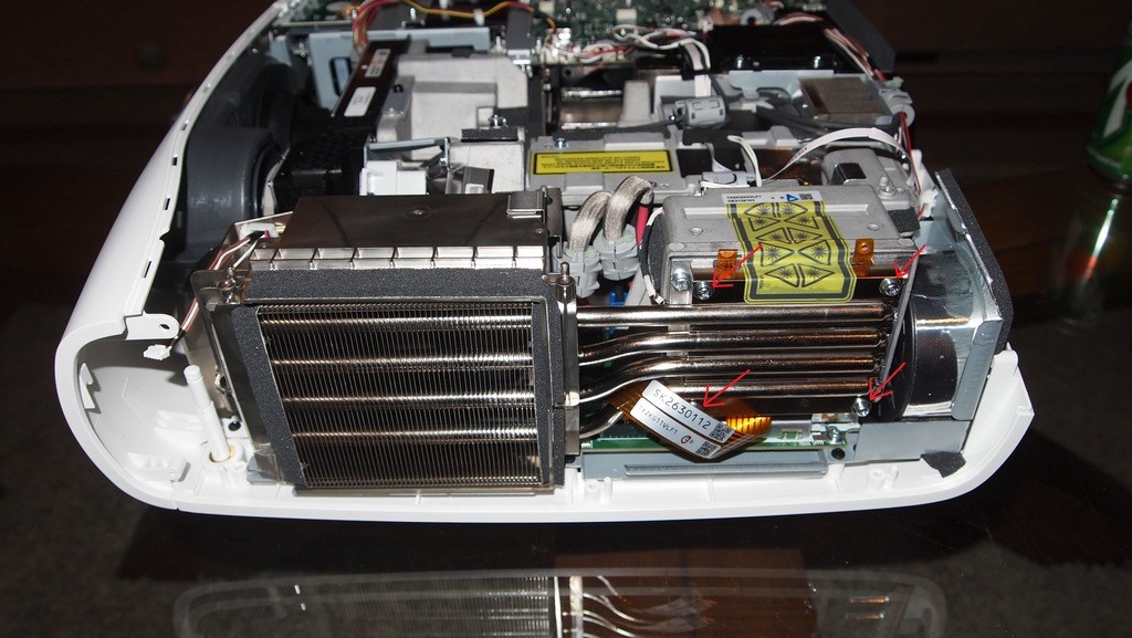
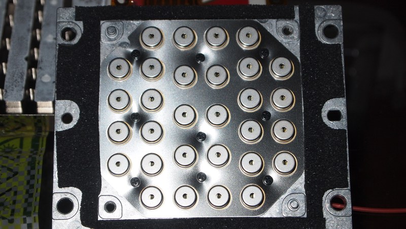
I have a set of two NUBM08 arrays (4x2 diodes each) that I would like to use as a source for a high power projector application (in a full enclosure, of course). From my reading, each diode laser array should produce a set of highly-parallel nearly collimated beams.

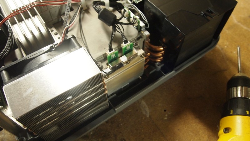
I know these laser diode arrays are used in projectors, and that there are commercial knife-edge mirror units with output lenses - but I don't have a good source for buying them, either new or as scrap from a teardown.

I have also considered trying to launch all of the beams into a large-core multimode fiber (1000um core or so) and I wonder if anyone has experience doing that. Can it be done with a single, large-diameter low NA lens (less than the fiber NA)? A fiber (1m-2m or so) would be convenient for coupling into the projector optics.

Anyone have some links that are helpful? Any tips or suggestions?

Thanks in advance -
 
Last edited:


Joined
Feb 12, 2016
Messages
589
Points
63
Hi ModeHopper,

Welcome to the Forum!

I am also pretty new here and do not know where to find cheap fibers, but regarding the Nichia blocks I was thinking to try knife-edging at least one array of it using micro knife edging unit from Lasertack. Maybe I do it in the future.

Here some suggestions (wrapped in paper is a 20mm sized PBS):

But Red Cowboy has written that 08 is not well collimated with original ball-lens, 06 array would be better to work with.
 

Attachments

  • 44 block-TEC 24.jpg
    44 block-TEC 24.jpg
    72.3 KB · Views: 861
  • 44 block-PBS-TEC 24.jpg
    44 block-PBS-TEC 24.jpg
    68.4 KB · Views: 543
Joined
Jul 10, 2015
Messages
9,882
Points
113
The NUBM08 ( Each individual diode ) with factory lens produces a 2 inch by 3 inch spot at 15 feet.

The NUBM06 ( Each individual diode ) with factory lens produces a 1 inch by 1/4 inch line at 15 feet.

For knife edging straight out of the block with factory lenses I would use the 06 not the 08.

The 08 likes 4.0 amps ( each diode ) and puts out 5+ watts with it's factory lens.
The 06 likes 4.5 amps ( each diode ) and puts out 5+ watts with it's factory lens.
Both make substantial by product heat.

NUBM06 with factory lens ( 1 diode ) at 15 feet. The burn mark is from the diode at 4.5 amps.
53199d1474400933-nubm08-array-sources-knife-edge-reflectors-fiber-coupling-strategies-nubm06withgballat15feet.jpg


NUBM08 with factory lens ( 1 diode ) at 15 feet. p.s. My camera is blocking the bottom left corner by just a small amount. The burn marks were already there, at 4.5 amps this diode can not burn at 15 feet with it's factory lens, if you had it in a massive heat sink and let it run for an hour it may leave a mark, LOL.

Both can be improved with a G7 or 3 element lens if removed from the block and installed in a module, or if you popped out the lens cans and made a threaded lens plate you could use G7 lenses as their focal length is around 7.5 mm.
53200d1474400933-nubm08-array-sources-knife-edge-reflectors-fiber-coupling-strategies-nubm08at15feet.jpg


The original K@$10 had a block of 24 1w diodes and a KE array that made a decent blue laser spotlight. The old 1w diodes had the best divergence, but it is still pretty bad, these are much worse.

This is a very old video but you can see how they diverge. You won't get a long range beam out of factory blocks, especially with factory lenses, you have to tear them down and do a lot of correction, and the divergence is still awful, they are after all multi mode laser diodes.


Attachments

  • NUBM06withGBALLat15feet.JPG
    NUBM06withGBALLat15feet.JPG
    207.2 KB · Views: 794
  • nubm08AT15feet.JPG
    nubm08AT15feet.JPG
    186.3 KB · Views: 781
Last edited:
Joined
Sep 20, 2016
Messages
8
Points
0
Thanks for the info and for the beam patterns. As stated, this is for a high power projector - I am not necessarily interested in best collimation performance (for a spotlight or pointer application). Fiber coupling may not be workable even with a large core, I was just going for some routing convenience there.

Are there any photos of the knife-edge optics used in factory projectors?

Also, I plan on driving 3A max (spec sheet value) - I don't want to push them too hard.

Thanks in advance -
 
Joined
Jul 10, 2015
Messages
9,882
Points
113
You can buy some HERE >>> https://sites.google.com/site/dtrlpf/home/knife-edge-arrays
NOTE these are for the smaller diodes in 24 diode blocks.

This is styropyros video, NOT MINE, the diode blocks are the 24 x 2 watt diodes with KE arrays for a total of 96 diodes, but at distance this is likely a spotlight. Still EXTREME caution must be exercised with these diodes, life long eye damage and blindness can happen from just 1 mistake, so protective laser glasses that attenuate the wavelength you are working with is a must.


The new bigger 8 blocks with lenses on the can don't have arrays to fit for sale that I have seen, I am curious about the method used to bundle the outputs, maybe conical/parabolic mirrors? Maybe a telescopic reduction optical train? I expect the KE arrays are no longer used.

Here's a pic, NOT MINE of 4 x 8 diode blocks, how do you think the beams are bundled?

YyWzcm.jpg

1y35Pa.jpg
 
Last edited:
Joined
Sep 20, 2016
Messages
8
Points
0
I have come across the DTR webshop linked above, but it says the knife edge arrays are out of stock, and I do think they are for different array blocks.

Does anyone have a diagram (or description) of the alignment of the linear diode output(s) and their orientation relative to the 4x2 array block? Is the long axis of the beam spot aligned with the long axis of the block, or are they perpendicular?

Definitely loud and clear on the eye and skin safety. Above 50mW I am a full-enclosures proponent. I have nice mate-to-skin certified goggles for these wavelengths, but prefer to work inside a metal enclosure at all times. Even powering diodes individually and with PWM, it is hard to align multiple beams at these power levels. No hi power handhelds for me.
 
Joined
Jul 10, 2015
Messages
9,882
Points
113
They are upside down top row to bottom, but otherwise all aligned the same.
The rectangle changes from tall and skinny to short and wide as the beam diverges because it's emission shape is opposite of it's divergence.

However that tricky can lens seems to square the beam up for inner machine distances.

Here is what comes out of a NUBM06.

I am running this at 4.5 amps, higher than factory spec.


I think they gave up on the KE array before the GBall lensed blocks, but I could be wrong, but what KE would be used with the 2nd pic?

bSxgmK.jpg

p1010009pt.jpg
 
Last edited:
Joined
Sep 20, 2016
Messages
8
Points
0
They are upside down top row to bottom, but otherwise all aligned the same.
Makes sense relative to all the hookup diagrams I have seen with the U-shaped PCB and serial power connection. I can see the index notches on the bases of the diodes also appear to confirm this.

However that tricky can lens seems to square the beam up for inner machine distances.

Does anyone have a clue what the nominal inner machine distance is, or what the next element is? The datasheet says that each diode's beam axis is at worst within 0.7 degrees alignment to all others. It would seem that a large plano-convex lens (large enough to catch the whole array) would place all the beams (16 for a double set) into a pretty small focal volume. If the planoconvex lens focal length is long enough (such that it underfills the NA of a fiber, often ~0.22 for larger multimode fibers), then a fairly-efficient launch will result.

Has anyone done something like this?
 
Joined
Jul 10, 2015
Messages
9,882
Points
113
I have not tried to get it all into a fiber, but I have thought about it, I would love to see it work...maybe with a Bragg grating incorporated at the ends?

Most of the blue light pumps phosphor to make green because green LD's are very inefficient, in the past it was a spinning disc.
Some projectors make red from blue with phosphor as well.

There are dichroic glass plates and the phosphor wheel that spins with a small gap for blue.
The old wheel looked like this:
The light mirrored tunnel at the top I have seen in projection DLP tv sets that use the old bulb too, I would like to understand those.
Maybe it's to fit the DLP chip?
50819d1459414701-phun-phosphor-20160331_043934-800x600.jpg


th


th
 
Last edited:
Joined
Sep 20, 2016
Messages
8
Points
0
The new bigger 8 blocks with lenses on the can don't have arrays to fit for sale that I have seen, I am curious about the method used to bundle the outputs, maybe conical/parabolic mirrors? Maybe a telescopic reduction optical train? I expect the KE arrays are no longer used.
That may be correct, I certainly haven't seen a KE that fits the blocks, either in teardown photos or for sale. A reasonable-sized planoconvex lens (~90mm dia) should be able to place a set of parallel beams into a decent launch area without too much fuss.

Not every large fiber is rated for >50W CW though, so that will take some work. Some have the epoxy near the ferrule tip removed so that it doesn't burn.
 
Joined
Jul 10, 2015
Messages
9,882
Points
113
Double clad fiber lasers are doped with ytterbium I think, but they make power inside the fiber from the energy of multi mode pump lasers in the kw range, often several joined, 1000 watts per unit and are stackable, I have no doubt that the right numerical aperture fiber could carry 50W no problem. A double clad with a high numeric ratio and possibly a blue light dopant?

Check out this video, it's not what we want to do because I don't think we want to pump just combine, but by pumping you get a much better beam quality.....I wonder what 450nm could pump, I know there is a dopant.

This video is 2 years old and advancements are already in use beyond this, but it covers basics and gives me some ideas about pumping with our little 7w projector bulbs, because multi KW stacks are in industrial use, they are replacing plasma and c02 as they are more cost effective and faster cutters, the beam quality and power have me drooling...well mentally drooling.

I do wood burning art with my little diode lasers and my hand speed and shading is still severely limited except at very close range, I need a lot more power, I am very safety conscious and have a concrete and cinder block basement and would build an additional concrete area to work with my ultimate goal of metal laser art and of course wear all needed safety equipment.
I have been thinking about fiber since my first fap 19 emitter laser, but those are just a bundle of 19 diodes, this is one high quality beam.
Forgive me if you already know this.

 
Last edited:
Joined
Sep 20, 2016
Messages
8
Points
0
Yeah, fiber lasers and ring lasers are cool. I don't know of any standard fiber lasers that are pumped at these wavelengths but wouldn't be surprised if there are several. As stated, I am mainly trying to get into the fiber for convenience of moving the beam to difficult (and variable) geometries.

Has anyone focused down an NUBM08 with the Gball lens intact? Any idea on the focal distance of the factory Gball?
 
Joined
Jul 10, 2015
Messages
9,882
Points
113
The emitter sits about 2mm above the diode backing plate and these lenses break when attempting to remove, there's a formed ridge that holds them in the can and the 08's are even worse.

My digital caliper is downstairs but here is the can length.

The actual distance from emitter to rear focal length is maybe 3 mm?

53210d1474470075-nubm08-array-sources-knife-edge-reflectors-fiber-coupling-strategies-sany0589.jpg


53211d1474470075-nubm08-array-sources-knife-edge-reflectors-fiber-coupling-strategies-sany0590.jpg


53212d1474470512-nubm08-array-sources-knife-edge-reflectors-fiber-coupling-strategies-sany0595.jpg


53213d1474470512-nubm08-array-sources-knife-edge-reflectors-fiber-coupling-strategies-sany0596.jpg


-----------------edit------------------

Ok wait a minute, why even use the GBall, a G2 is a better lens, if you're going to pull the GBall then just use a G2 and it's rear FL is 2.39mm

DTR metered the 08 with the factory GBall and a G2 and the G2 was more efficient by about 5%

I would like to keep the GBalls intact for future use, but I am thinking I am going to move to IR anyway, the can/window diodes in my experience seem to be more robust.

If you already have the NUBM08 blocks then ok, but NUBM44's are better diodes, just 5nm higher frequency and a tad more efficient.

Here is a NUBM06 with a G2, it focuses so tight it cuts wood without igniting it.


To get into a fiber some NDB7875's with G2 lenses as they are can/window diode with a tighter emitter would be a good test and they are tough and cheaper only half the output, but the emitter size could be a win.
 

Attachments

  • SANY0589.JPG
    SANY0589.JPG
    199.9 KB · Views: 726
  • SANY0590.JPG
    SANY0590.JPG
    182.6 KB · Views: 719
  • SANY0595.JPG
    SANY0595.JPG
    168.7 KB · Views: 665
  • SANY0596.JPG
    SANY0596.JPG
    170.2 KB · Views: 676
Last edited:
Joined
Sep 20, 2016
Messages
8
Points
0
Well, it turns out, it is definitely possible. Shimadzu has a line of products that start with a collimated array of blue diodes (3x3 in this case) and use a simple lens to go into small multimode fibers - One such unit outputs 20W CW from a 200um multimode fiber core.

Angular dependence of screen speckle and fiber speckle of coupled output of nine high-power blue laser diodes through a multi-mode fiber:

Angular dependence of speckle contrast of speckle pattern projected out of a multi-mode fiber connected to a high-power blue laser module is investigated. The laser module has nine high-power InGaN/GaN blue laser diodes arranged in a three-by-three array. Each of the arrayed laser diodes have slightly different incident angle to the fiber. We have successfully extracted the fine screen speckle pattern from the projected pattern mixed up with the coarse fiber speckle pattern by processing the measured data. It is found that the speckle contrast of the both screen and fiber speckles are larger around the center area where the guided-light component closest to the paraxial direction is projected. This is because the output of the center laser in the array is likely to couple into the paraxial mode more than the rest. Speckle contrast behaviors when applying the speckle reduction methods, fiber vibration, diffuser, and spinning diffuser are also investigated.
 
Joined
Sep 20, 2016
Messages
8
Points
0
Fiber-Coupled Blue Direct Diode Laser BLUE IMPACT series HK-5650 (BLUE Semiconductor Laser Module) : SHIMADZU CORPORATION

This one is listed as 10W from a 100um multimode core diameter - but the paper cited above describes 20W from a 200um core. It seems the application is copper and gold material processing. At any rate, the paper has a diagram which is pretty much a 3x3 collimated array going directly into a single lens element, and then into the multimode fiber. Granted, the lens itself might be a complex multielement, but for these lasers, almost any good planoconvex will do a decent job since there isn't much chromatic aberration. I think a nice slow low-NA planoconvex will launch well into a big multimode fiber.


Top