Welcome to Laser Pointer Forums - discuss green laser pointers, blue laser pointers, and all types of lasers

LPF Donation via Stripe | LPF Donation - Other Methods

Links below open in new window

ArcticMyst Security by Avery

Need a NUBM31T PWM driver -- Killing chinese ones.

AshSerigala

New member
Joined
Nov 14, 2021
Messages
6
Points
3
Hello! Would like to mention I'm not "new" to the forums, I had an account since 2010 ( User: jbtm ) but that email address is far lost so I figured I'd just make a new one. I own a NUBM31T 455nm 95W Laser array. I've been trying to find a driver for it that allows for PWM control, so I can use it with a laser etcher/cutter. I already got all the optics figured out, beam correction and everything. Beaming it down XYZ rails and hot focal point. Thats all A+ working great no problems. My issue is finding a controller. I've tried two from china so far. Identical controllers from different sellers, and both failed. Both drivers would output 100% laser power ( Constant voltage Constant current ) at 000% PWM. 1% or higher would just put out nothing. Then, Using a volt meter, Amp meter, and scope, I verified everything was proper voltages for the PWM system to work..So, I'm just delcaring it a fake product by now.

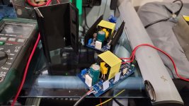
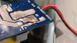
The biggest issue with them, if I run the laser at 81V 2.9A, after 30 seconds smoke gushes out of the driver. I said F it and just let it 'do its thing' and turns out a PCB trace just blew out, that's what was getting too hot and causing the smoke. This trace was the +12V from powersupply to mosfet. Their tiny tiny underated 25V 1600uF capacitor also gets BURNING hot to the touch when doing 3A which tells me it cannot handle the ripple current of the driver.

Like said, I tried two of these drivers. They both didn't work. Even tried one that came with a PWM controller -- the PWM part of the driver STILL didnt work. So.. Being out like $100 now on failed drivers, I figured I'd ask if anyone has something to recommend me. I have a good $300 invested in corrective optics..so I'd like to get this thing working with 1-100% duty control. Amazes me I havent killed the array yet with how poor of luck I'm having with these chinese drivers. I figured they'd be plug-and play. PWM/TTL working and all. Nope!!!! All fake products.

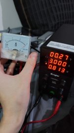
I mean, it works, It does indeed put out 81V and does indeed let me adjust current draw very very fine. But unless I beef up the trace and replace the capacitor with a low ESR,high current rated one, its a problem. Then theres the fact the PWM doesnt work at all. Which idk. I thought of putting a mosfet on the 81V side and using that PWM driven, but that could piss off the constant-current controller. Bleh.

They claim:
- Input power: 12V 7A
- Output power: Rated 85V 3.3A max

So, 84 Watts input, 280 Watts output. They've developed a free energy machine oh no..
 

Attachments

  • Driver1.jpg
    Driver1.jpg
    94.5 KB · Views: 10
  • Driver2.jpg
    Driver2.jpg
    67.9 KB · Views: 10


Unown (WILD)

Well-known member
Staff member
LPF Site Supporter
Joined
Sep 4, 2020
Messages
1,447
Points
113
Ah welcome back! Which account do you want to keep? Can't have two on here. Do you want to use this one and just forget the old one or do you want to figure out the email addy and use the old one?
 

AshSerigala

New member
Joined
Nov 14, 2021
Messages
6
Points
3
Ah welcome back! Which account do you want to keep? Can't have two on here. Do you want to use this one and just forget the old one or do you want to figure out the email addy and use the old one?
Is that actually a thing here? I guess I never looked at that rule since I normally would never expect to have two accounts haha.

I know for a fact my old account is under an email address I actually lost control of. Near 90% sure. I wouldnt be against having access back to that account though. As back then at least, I remember theres times we had people on the forums who sold diodes/drivers, and they'd only sell them to people with certain rep levels or people who proven themselves out. So we're not selling parts to people who may burn an eye out. I wouldnt be dorking with a 95W array chip if I didn't already have years of experience with lasers to understand the risks involved. I guess for that sakes, it makes sense to maybe have that account's email address changed if possible. I didn't bother checking if it was tagged to an old gmail account I do have access to, but I'm very certain its on the hotmail account I lost and moved on from.


As an update to this question/topic. I decided I'm gona F around with the idea of those 0-120V 3A power supplies found on amazon. The ones with CC/CV. From my experience, these have been pretty stable, and you can fine-adjust them to be 81.0V 3.0A. The 36V one I currently have, I put a mosfet on the output of it and connected it to a 25-ohm resistor and some LED strips. Using 1khz PWM signal, I was able to go from 0% to 100% duty cycle and see the LED strip go from dim to bright. The power supply adjusted the volts/current as needed when I ran it in a CC mode. Nothing I tried pissed off the power supply, so I feel it should work for the laser. I'll just have to put a volt/amp meter on and use a scope to watch everything, just to verify no spikes are happening. But that's the best solution I can find so far. This wont be portable. This will be built into a table, with the laser. Set-and-forget.
 

Unown (WILD)

Well-known member
Staff member
LPF Site Supporter
Joined
Sep 4, 2020
Messages
1,447
Points
113
I wish I could tell what email address is linked to the account but we moved to xenforo software a few years ago and a lot of features are lacking in that department. Otherwise I'd help ya get your old account back up and running.
Good luck on the project. Yeah you can never trust what the chinese rate their products as. It's always a gamble
 

AshSerigala

New member
Joined
Nov 14, 2021
Messages
6
Points
3
Ahhh okay. Because yeah. I can tell you the old account was jbtm and if you had a way to change that info as means of "Proving you own the account" proving it wouldnt be hard since the user icon is a project I got many photos of etc etc. But if you dont have the ability to change the email address over so I can request a password reset and such then I guess its best to have jbtm account deleted, as I have no access to it and it'll forever sit inaccessible xD
 
Joined
Nov 2, 2015
Messages
74
Points
18
Yes, I've been down this road with that driver. I had to 3D print a fan mount for the PSU because of overheating issues. I made a short write up as to how you can implement your own PWM interface: https://metalmatters.co/showthread.php?tid=7

20211116_033519.jpg

With all that said you probably are better off just getting that PSU from amazon.
 
Last edited:
Joined
Feb 12, 2016
Messages
589
Points
63
I did not try PWM but I had a thread about how bad this so called "Driver designed for NUBM31" was.

Even the 5usd 250W specs driver from ebay performed better if it was properly sinked.

BTW I also tried to drive one NUBM31 with 2 drivers for NUBM08 blocks from ali set to 40V, 3A. Each was OK to drive 2 rows from 4.
They have a kind of TTL/PWM? switch and laser turns on/off when you give 0.5V to the small contacts.
In specs they wrote 5V input for control but when I tried - 0.5V were enough to switch the laser on.
 
Last edited:

AshSerigala

New member
Joined
Nov 14, 2021
Messages
6
Points
3
Yes, I've been down this road with that driver. I had to 3D print a fan mount for the PSU because of overheating issues. I made a short write up as to how you can implement your own PWM
The problem with both of mine, is the PWM never even worked. I was sending 5V signal to it and even used the signal generator they supplied with it ( 5V output, 0-100% duty adjust and 0-150khz freq ) using a scope i confirmed 1khz..10khz..and 15khz, 0-100% duty. Nothing worked on both drivers i had. 0% made it go 100% power, and 1% all the way to 100% did no output at all. Im not sure if your link/mod suggested, fixes that? But I can try it if you think its worth it. Running 100% power ( 81V 3A ) the diodes typical rating, burned the pcb trace clean off within 30 seconds. Smoke seen within 10 seconds or so.

The amazon bench power supplies ( fine adjust voltage/current ) run about $90. 0-120V 3A. Can set to 81V 3A max current for CV/CC. So long as theres no spikes from the PWM, it should be fine. And with the teensy chips I use, it'll give me more fine resolution anyways, since I can do 0-8192 ( or higher ) pwm values. Up to 13 bits. I did buy one, so I'll give that a try and proceed with caution and report my results
 
Joined
Nov 2, 2015
Messages
74
Points
18
The hardware expects a current sourcing TTL signal. The signal on the PWM pins has to be pulled low by a transistor, bridging the two pins, to effectively switch the unit off (as its default is on). I'm guessing you're driving the PWM input with something CMOS based which won't be able to handle the current which is why you're seeing that odd behaviour. I ended up testing this out and it still left me with 80% deadband at 50 - 250 Hz IIRC. If you setup the unit as I've illustrated you will be able to drive it from a CMOS source with the deadband reduced to around 33%. You might be able to get more out of it by tweaking the resistor values (Keep in mind the resistor values are setup for a 3V PWM signal). It will also ensure the units default mode isn't on as this is pretty dangerous and impractical to work with. I can't comment on whether you'll be able to drive it at higher frequencies. The frequency response for the shutdown pin might be listed in the datasheet.

I'm not sure what the ESR of that capacitor is but I bet it's too high - probably very inconsistent between units also. If you want to try this method it would be worth while replacing it and adding solder to the tracks to give them better current handling capacity.
 
Last edited:

AshSerigala

New member
Joined
Nov 14, 2021
Messages
6
Points
3
The hardware expects a current sourcing TTL signal. The signal on the PWM pins has to be pulled low by a transistor, bridging the two pins, to effectively switch the unit off (as its default is on). I'm guessing you're driving the PWM input with something CMOS based which won't be able to handle the current which is why you're seeing that odd behaviour. I ended up testing this out and it still left me with 80% deadband at 50 - 250 Hz IIRC. If you setup the unit as I've illustrated you will be able to drive it from a CMOS source with the deadband reduced to around 33%. You might be able to get more out of it by tweaking the resistor values (Keep in mind the resistor values are setup for a 3V PWM signal). It will also ensure the units default mode isn't on as this is pretty dangerous and impractical to work with. I can't comment on whether you'll be able to drive it at higher frequencies. The frequency response for the shutdown pin might be listed in the datasheet.

I'm not sure what the ESR of that capacitor is but I bet it's too high - probably very inconsistent between units also. If you want to try this method it would be worth while replacing it and adding solder to the tracks to give them better current handling capacity.
A friend of mine who makes SMPS for a living did rough math on it and said hes surprised it doesnt just detonate itself. At 81V 3A it gets >90F on both my drivers. Would need like 4 of them to be even remotely practical.

Im powering it off the PWM controller they gave with the unit. To my scope, it puts out 5V and when switching its not dipping, its staying a strong solid 5V. But anything over 0% duty just makes the laser turn off whole 0% duty is full on. I even tried inverting the signal. This was the case of both drivers. The ebay seller said its connected right and still said its my fault its bot working. Very unhelpful. Since they're paper weights, ill repair the fried trace with a jumper wire and do the mod you linked me. The drivers still work 100% after that trace blows, as thankfully the mosfets are rated way more than what the driver can handle! Im willing to bet that trace is only rated for the 12V 7A input power they spec despite 81V 3A Would require a 12V 24A supply!

Edit: I'm honestly not against the idea of running each string of diodes on 4 drivers even, for example. and doing a PWM on all 4 drivers. Then I have the ability to do even lower wattage when needed by only running 1 driver. Even though that means I could potentially put more wear on 1 set VS the entire thing. I guess that's an option to look into too. 81V 3A for all 20, thats like what.. 20.25V 0.75A per row, if I was to run 4 drivers, or 40.5V 1.5A per pair of 2 strings in series, if i ran 2 drivers..

81JEbv4yIKL._AC_SL1500_.jpg


You can find drivers like these for example and its like yeah, No one really offers PWM driveres to modulate 0-100% for laser etching/cutting use. You can just assume/hope the chips they use allow a "Enable" pin to be modulated and hope that doesnt F anything up. Or add a mosfet on the output and hope firing that mosfet 0-100% duty doesnt piss the driver off.
 
Last edited:

AshSerigala

New member
Joined
Nov 14, 2021
Messages
6
Points
3
So quick update! I got the new power supply in. This is a 0-120VDC adjustable supply. You set the voltage to 5VDC, then short the leads and set your current limiter. Set it to 3Amps and put the voltage to 80V and connected it to my array, with a MOSFET in series from the power supply and the array. 1Khz signal, 0-100% duty. At first...Nothing. No matter what % I was zero output. Then I noticed something bad. The power input pin, freely rotates. I knew this was a risky setup and it was NOT made to be the final. I have a PCB ready to solder it to. Go figure, the pin rotates loose and no connection anymore no matter what I do.

So. That aside. I skipped that row and used the next at 64V. 1% duty does nothing. 2% duty is VERY dim. and anything higher gets brighter. Testing on a 25Ohm resistor for 81V 3A, i can do 0-100% with no complaints. so YAY the power supply doesnt care.

Its just yeah. I have a dead row now because dumb setups. Fully my fault. and its sad because this was going to be fixed to a PCB like once before.. Oh well. Not a major loss, its just more square now ( which is good anyways ) and I can always order another and call this the abuse/test array. Either way im just happy to see I can mosfet PWM this benchtop power supply with zero complains. Dead quite, the internals dont whine or complain.

To be clear, the row still works. Sometimes you can get a spark of blue light. But nothing keeps it constant, and im not gona cause myself potential hazard taking that risk. Will just keep it to 4 rows.
 

Attachments

  • photo_2021-11-19_14-44-59.jpg
    photo_2021-11-19_14-44-59.jpg
    75.1 KB · Views: 6
  • photo_2021-11-19_14-46-47.jpg
    photo_2021-11-19_14-46-47.jpg
    66.1 KB · Views: 6
Last edited:

likevvii

Member
Joined
Mar 2, 2020
Messages
74
Points
18
I currently use this driver for 100% duty cycle, but I believe it may be well suited for clean PWM control.
Maiman Electronics SF6060
https://www.maimanelectronics.com/product-page/high-power-laser-diode-driver-oem-cw-15а-40v-sf6060
Unfortunately, this requires the array to be used in all parallel configuration. And also expensive!

I have tested the NUBM31T arrays in 4P1S configuration and the maximum current deviation at 3.5A is around 0.25A
Modern high powered blue diodes are so robust, they are almost like high powered LEDs. they can take some serious abuse!
 
Joined
Nov 2, 2015
Messages
74
Points
18
That's an incredibly expensive little PSU likevvii. Hope you're making the most of it.

These diodes are surprisingly robust. 85mA reverse current and a temperature limit of 70C. I have a couple of fiber coupled diode lasers and they aren't anywhere near as tolerant, although they do have a much larger surface area to emit heat from.


Top