- Joined
- Sep 3, 2010
- Messages
- 61
- Points
- 8


Follow along with the video below to see how to install our site as a web app on your home screen.
Note: This feature may not be available in some browsers.


Thanks for the resizing demand, Paul. Much better. Now that it's fourteen pixels wide, I can't see a damn thing.
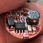
Mr. Sterbs, please read off the letters on the IC and I can probably tell you all about it, including the current setpoint.
Looks like you need to get aOMG, you need to resize these as they are too large for anything around here. I'm sure one of us has seen this before, once I can see it well enough.

")
I don't understand why the OP doesn't just connect it to a dummy load and measure the dang thing. If I had it here, I would have already done that and this whole thread would be pointless.
Well, the datasheet says it's a 2A buck regulator with a feedback voltage of 1.222V. That doesn't make sense with the 120mΩ shunt though. The other common feedback voltage would put it nearer to 1.8A, but it certainly isn't above 2A with that teeny inductor.
I'm not sure the R120 is actually the current set resistor though - photos lack the detail to trace it out to the feedback pin or anything else.
I assume the chip is http://www.yobon.com.tw/pdf/YB1682 Rev.1.0.pdf based on the markings stated, but without a view of the complete circuit it's hard to tell what's going on here.
I agree it's doubtful that this is pushing anything in the order of 2 amps with that small inductor, although the chip itself is capable of it.
If you are in the midst of moving, you can't use it right now anyway. Once you get moved and can get your "kit" then you will have need to know what current it is set for.