WOW dude, that's exactly what I meant, thanks for the diagram. Actually you have to use a 1 ohm resistor, that way you don't have to divide the current by anything, (the easy way) ;D but if you don't have one, then you can use any resistor, and then divide the voltage you get by the resistance of the resistor, e.g. if it's a 5 ohm you divide by 5, if it's 7 then you divide by 7, etc.

Welcome to Laser Pointer Forums - discuss green laser pointers, blue laser pointers, and all types of lasers
How to Register on LPF | LPF Donations

Navigation
Install the app
How to install the app on iOS
Follow along with the video below to see how to install our site as a web app on your home screen.
Note: This feature may not be available in some browsers.
More options
You are using an out of date browser. It may not display this or other websites correctly.
You should upgrade or use an alternative browser.
You should upgrade or use an alternative browser.
Modifying the DDL circuit
- Thread starter SargeMX5
- Start date


- Joined
- Oct 27, 2007
- Messages
- 320
- Points
- 0
thanks man, here's the upgrade of your guide. ;D
- Joined
- Oct 27, 2007
- Messages
- 320
- Points
- 0
- Joined
- Oct 27, 2007
- Messages
- 320
- Points
- 0
no problem man,im just adding help for our brother to understand the basics. ")
- Joined
- Oct 27, 2007
- Messages
- 320
- Points
- 0
hey chido after he got the current value, what he gonna do next? before the actual attachment of the LD, do you think he was going to take out the LD and the resistor, then place the actual LD on it? whats the idea here? ")
The idea is to test the circuit with a dead LD or the 4 1N4001 silicon diodes (as seen in the first page) to make sure it's working properly, then when he gets his new LD he can solder the capacitor onto it, solder the negative wire from his driver to the LD, adjust the current going to the diode how it's posted above, and finally solder the positive wire from the driver to the LD.
- Joined
- Oct 27, 2007
- Messages
- 320
- Points
- 0
ok then so he will use the current he gets on the actual test, right?
- Joined
- Oct 27, 2007
- Messages
- 320
- Points
- 0
man i post it already cuz its just sounds interesting to me, and make some quick change before i finalize my project.
- Joined
- Oct 27, 2007
- Messages
- 320
- Points
- 0
ok thanks, and please tell me why the voltage out of my driver was higher than 3volts in current of 210ma, I test it open circuit without the LED attached, please post your response on my new thread , thanks.
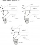
Ok. The +ve leg on my dead diode snapped off. I dont have any 1N4001's but i did have 1N4004. I got a 1ohm resistor. I wired it up in the diagram which someone else posted somewhere about how to test the DDL driver. At 3.08volts, i was reading 89mA at lowest resistance and 13.9 with max pot resistance. This doesnt sound right. Are the 1N4004 diodes interfering with my readings and causing an unexpected result?
Did you set your multimeter to mV, some times the readings can look weird if it's not set to mV. Also, I just checked out the 1N diodes datasheet and they all appear to have the same voltage drop so I don't think that's the issue. Did you read the last post on the first page, I told you exactly how to test the driver. It doesn't look like you're testing the circuit right, if you're using a 1ohm resistor, then whatever V you get in your DMM when set to mV will be your current. Can you post a pic of how you're testing the driver?
Gazoo
0
- Joined
- Jun 9, 2007
- Messages
- 3,206
- Points
- 38
SargeMX5 said:Ill get a couple of pictures of the test circuit and the two points in which i am probing and a picture of the readings on the multimeter very very soon.
I noticed you said you were using 4 aaa alkaline batteries. And chido suggested you bump up the voltage, but I don't see anywhere you acknowledged his suggestion. You absolutely must use a minimum of 6 alkaline or nimh batteries. Nimh batteries are very much preferred over alkaline batteries because they withstand the higher currents being drawn from them much better. The rule of thumb for the voltage going into the regulator is it should be 3 volts more than the voltage going to the diode. A SenKat diode running at 250ma's will have about 3 volts across it. Therefore a minimum if 6 volts is needed. Granted an alkaline battery is rated at 1.5 volts. But as soon as you begin to draw current from them the voltage will sag considerably and the regulator will begin to drop out if you are only using 4 batteries.