- Joined
- Feb 5, 2008
- Messages
- 6,252
- Points
- 83
Hiya folks, lack of my PART II on LPM project is more than visible.
I've been bustin my head over the board and debugging - well
Long story short , I took for granted that the professors who helped design the PCB knew what they were talking about.
First , the ULN2003 , seven darlington arrays, to drive LED segments because the port output is not powerful enough .
Fine, well, after 2 days of bustin' my head I finally understood what the problem was , CATHODES of segments are to be connected into OUT ports of ULN, hence, I needed to pick up entirely new displays, common ANODE.
Corrected that, and wired everything, and rewired (PCB is 2 mm thick, cannot solder on top side for displays and MCU socket, so everything that was display and socket connected on top side was rewired on bottom side, with airwires, or jumpers. Pretty sight, around 30 wires on bottom side. ).
Okay next , when the thing is powered WITHOUT MCU in it's socket , all of segments light up.
When a wire is socketed in GND pin of MCU socket, and when I touch various port pins, segments turn off.
Is i not supposed to be other way around, instead of turning the off with 0, we should light them up with 1!
Damn.
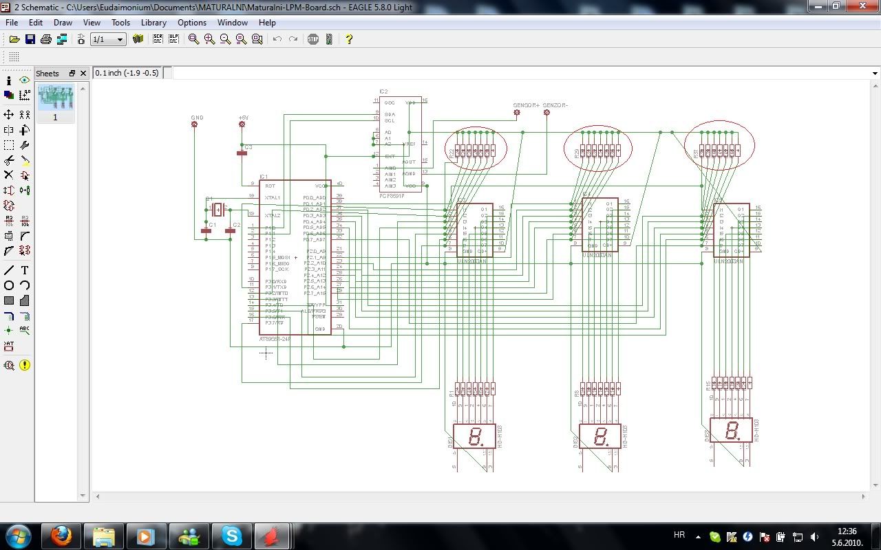
Well, I want all you to look at the schematic.
Push up resistors, the ones in red circles, for what exactly are they needed, by my logic, they are to be completely removed.
I appear to made the same mistake twice, professors do not know what they were suggesting me
"Yes you need those resistors"
They are 4.7 k Ohms.
So far I've figured that if those are removed, segments would be lighted up by 1, and none would light up on powerup without MCU in there.
Am I correct?
Is there anything else wrong with the schematic?

I'm running real tight on time, and I need help ASAP.
Thanks!
EDIT - cutting out those resistors can be done in 3 seconds , leaving only their pins to give the connection that need to be there.
I just need somebody to confirm my suspicion, that they are not needed and they are indeed causing trouble.
I've been bustin my head over the board and debugging - well
Long story short , I took for granted that the professors who helped design the PCB knew what they were talking about.
First , the ULN2003 , seven darlington arrays, to drive LED segments because the port output is not powerful enough .
Fine, well, after 2 days of bustin' my head I finally understood what the problem was , CATHODES of segments are to be connected into OUT ports of ULN, hence, I needed to pick up entirely new displays, common ANODE.
Corrected that, and wired everything, and rewired (PCB is 2 mm thick, cannot solder on top side for displays and MCU socket, so everything that was display and socket connected on top side was rewired on bottom side, with airwires, or jumpers. Pretty sight, around 30 wires on bottom side. ).
Okay next , when the thing is powered WITHOUT MCU in it's socket , all of segments light up.
When a wire is socketed in GND pin of MCU socket, and when I touch various port pins, segments turn off.
Is i not supposed to be other way around, instead of turning the off with 0, we should light them up with 1!
Damn.
Well, I want all you to look at the schematic.
Push up resistors, the ones in red circles, for what exactly are they needed, by my logic, they are to be completely removed.
I appear to made the same mistake twice, professors do not know what they were suggesting me
"Yes you need those resistors"
They are 4.7 k Ohms.
So far I've figured that if those are removed, segments would be lighted up by 1, and none would light up on powerup without MCU in there.
Am I correct?
Is there anything else wrong with the schematic?

I'm running real tight on time, and I need help ASAP.
Thanks!
EDIT - cutting out those resistors can be done in 3 seconds , leaving only their pins to give the connection that need to be there.
I just need somebody to confirm my suspicion, that they are not needed and they are indeed causing trouble.
Last edited:


