Hi Everyone,
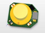
First time at this forum. I've done a bunch of research and I'm trying to build an EXTREMELY small (as small as I possibly can!) circuit board with the Sanyo voilet Laser diode DL-4146-101S including the driver circuit (I've attached the schematic). I've also attached a picture of what the PCB would look like. I found a DBGA LM317 that is 1mm x 1mm in the upper right corner. Could I get some feedback on what you guys think? Does the circuit look OK? Could there be issues with packing the circuitry so tight?
The reference voltage on the LM317 is 1.25V so the 37.4ohm resistor should force the current to be about 33.4mA at 25C which is a little below typical operating voltage, but above the threshold.
The PCB is 8 x 6.5 mm
Sanyo LD Data sheet link
http://www.thorlabs.us/Thorcat/22000/DL4146-101S-MFGSpec.pdf
Thanks guys!
Devyn


