Welcome to Laser Pointer Forums - discuss green laser pointers, blue laser pointers, and all types of lasers

LPF Donation via Stripe | LPF Donation - Other Methods

Links below open in new window

ArcticMyst Security by Avery

LMS1587 based linear driver

Joined
Mar 25, 2011
Messages
8
Points
0
Your circuit looks good, the board is harder to tell because I can't see it very well, but also looks OK to me. If it passes the DRC and ERC fine then you should be in the clear.
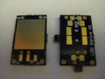
What's the size of the finished board if you don't mind me asking? Around 11x15mm?

As you said, your power rating will go up to 4w, but the resistance will also become half if you use two matched resistors.


Glad to see that you're using James for your PCB, the place he uses is really good and gets the boards out quickly.


Joined
Feb 9, 2011
Messages
578
Points
0
I tried to make the board as small as I could without getting errors. Unfortunately, the final board size is a little bigger than I wanted. It's 12x18mm due to the IC package size. :( I ordered 6 boards. I'll probably update my board later on if need be. I love the purple soldermask!
 

rhd

0
Joined
Dec 7, 2010
Messages
8,475
Points
0
I'm struggling with something that may not be an issue, but I just wanted to run this by you in case -

From your design, I can't tell where the 3rd case pin is attaching to the board. All I can tell for sure, is that there are two case pin connections on your board.

What troubles me (and this may just be my incorrect reading of your PCB layout - I'm not terribly experienced with this) is that I'm assuming you get 2 connections via pins, and 1 connection via the case of the IC.

Well - it looks like your center IC pin has it's own connection. If the pinout of this regulator is similar to the LM317, 1117, etc, then the center pin is the same as the IC case. So I'm just wanting to double-check that you've got the pinout correct?

Again - just an observation from someone unfamiliar with your IC - but I wanted to double check.
 
Joined
Mar 25, 2011
Messages
8
Points
0
That is why I said it was hard to see. I was having identifying everything.

From what I can tell:
If you look at the bottom center you'll see 3 red pads.
The left two connect to resistors (for the current limiting) and the rightmost connects to the positive power through a decoupling cap. The giant red square is the "heatsink" for the LDO regulator... if you run it with a small voltage source, it shouldn't heat up much at all.

The green vias on the top side are for the LD and the bottom are for power source.

While the remaning components from top to bottom are capacitor, diode, two resistors, and capacitor.

It seems that there's a grounding plane on the top side that isn't filled in but it facilitates most of the negative/grounded connections. (Perhaps even a grounding plane on the bottom as well? Otherwise where do the decoupling caps connect?)
 
Last edited:
Joined
Feb 9, 2011
Messages
578
Points
0
Sorry, It's hard to tell because I did not run the ratsnest when I took the picture, but Personmans is correct. If you look at my schematic they are connected to the ground plane, which is only shown when you run the ratsnest. All you can see there is the pads, vias, pins, and traces.

I'm gonna make a board using that IC you showed me but it seems I won't finish it by the deadline for submission :(. So it will be in the next batch, which is sometime mid April. It's spring break so I have plenty of time to experiment :evil:

Edit:
That IC you showed me gave me and idea to use the enable as a safety switch device. Instead of connecting it to V+, you could run a separate wire. However, this requires another switch, which when on allows connection to the battery. This could be a very promising driver =]
 
Last edited:
Joined
Feb 9, 2011
Messages
578
Points
0
Ok, I have been away for a few days, but I received my driver PCBs on Saturday and I've been playing with them. :san:

attachment.php


attachment.php


attachment.php

Sorry, It's kinda messy because I didn't clean off the flux yet. :p 
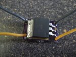
and I know my soldering is messy :yabbem:

They work as expected! However, I did run into some problems.

-Driver is outputting more current than calculated based on a PHR-803T LD.

Calculations:
> Current setting: Vref/Rset so 1.25/11.5=108mA
> Voltage needed: Vdo (blu ray) + Vdo (regulator) so 4.5+1.2=5.7V

Actual test:
With my 2 CR123 batteries outputting 7.4V I get over 130mA on my test load. So I tested again using a 6V lantern battery at 6.11V but it only outputs 79mA.

Since this is suppose to be a low drop out regulator it seems I am needing at least 7.2V to achieve my desired current versus my calculated 5.7V. Which is an improvement I guess since a LM317 would need 7.8V-9V to drive a blu ray LD?
 

Attachments

  • IMG_0114.JPG
    IMG_0114.JPG
    95.4 KB · Views: 815
  • IMG_0123.JPG
    IMG_0123.JPG
    151.3 KB · Views: 985
  • IMG_0124.JPG
    IMG_0124.JPG
    154.4 KB · Views: 1,021
Joined
Mar 25, 2011
Messages
8
Points
0
Cool, great to hear that they work.

I'm sorry if this sounds insulting, but perhaps the protection diode is on backwards?
4.5+1.2+0.7 = 6.4, so your 6.11v source wouldn't cut it.

Does seem to operate a couple volts lower than the LM317 though, how is the heat? Do you notice a difference?


As far as the 130 vs 108mA, I'd double check the resistor with a meter. Most of mine are 5% resistors so an 11.5 could be ~10.93ohms or ~12.08ohms, though that still only lands you at ~114mA max.
 
Joined
Feb 9, 2011
Messages
578
Points
0
No, I'm sure my diode is on right otherwise it wouldn't work at all since diodes only allow current to go one way.

And I've checked my resistor with my meter and it is indeed 11.5 ohms. It's 1% tolerance. And for heat it is barely warm to the touch. I can't wait to start my new build. I ordered extras for future builds and If people want to purchase some boards and or complete sets.
 
Joined
Mar 25, 2011
Messages
8
Points
0
If the diode were in backwards it would be in parallel with the LD, so the whole setup would still work as expected... well, it wouldn't protect your LD and your voltage drop would be higher, but it would lase still.

Still puzzled on the expected vs actual current output. Have you tested voltage between ADJ and VO to make sure it's 1.25 as expected? I'm sure it is, but I'd check anyway.
 

rhd

0
Joined
Dec 7, 2010
Messages
8,475
Points
0
Here's what's wrong:
> Voltage needed: Vdo (blu ray) + Vdo (regulator) so 4.5+1.2=5.7V
A) you're missing the VRef resistor drop of 1.25V
B) your Vf (blu ray) should be more like 5.3V (citation)

Should be:
> Voltage needed: Vdo (blu ray) + Vdo (regulator) + VRef Drop so 5.3+1.2+1.25=7.75V

Explanation of that second point:
Your regulator may only drop 1.2 V, but remember that figure is given for when using these regulators PROPERLY as voltage sources. We're not doing that. We're relying on Ohm's law, and the fact that these little ICs work to maintain a constant drop across VOut and VAdj of 1.25 V.

Again, that's an ADDITIONAL drop created by the resistor, and it isn't factored in to the datasheet value. So an IC with a stated drop of 1V, will also have an additional 1.25V drop because of the VRef when used in our DDL circuits.

At least, this is my latest understanding of the tech, and I really want an authority to step in and verify.
 
Joined
Mar 25, 2011
Messages
8
Points
0
Yeah, I think you're right rhd. My LM317 notes say ~3v dropout -- 1.25 for the Vref and 1.5+ for the voltage regulator itself.

Thanks for the insight.
 

rhd

0
Joined
Dec 7, 2010
Messages
8,475
Points
0
The only weird thing - is that the LM317 datasheet actually says ~2.5V dropout for the regulator.

I think the voltage dropouts in datasheets cannot be taken literally when using them as current sources, but rather are only useful for comparing ICs relative to each other.
 
Joined
Feb 9, 2011
Messages
578
Points
0
Ok, so in relation to Vref I have tested and came up with these results.

Testing at 6.03V:
Vref (measured) = .85V
Output current (measured) = 74.5mA
Vref/Rset = .85/11.5 = .073 = 73mA

Testing at 7.4V:
Vref (measured) = 1.5V
Output current = 130mA
Vref/Rset = 1.5/11.5 = .130 = 130mA

It would seem that Vref is somehow related to output current and makes me confused because Vref should be 1.25 as stated in the datasheet.

And I also measured the drop out voltage of the resistor which is the same as the Vref.

Vref = Vdo of resistor

My test load is set up to 6 diodes which gives a voltage drop of 4.2 (0.7V*6 = 4.2). Nice find for the graph though! I could use that.
 
Joined
Mar 25, 2011
Messages
8
Points
0
Thanks for measuring that, Jufran88. It seemed weird to me that it was outputting too much current.


The only weird thing - is that the LM317 datasheet actually says ~2.5V dropout for the regulator.

I think the voltage dropouts in datasheets cannot be taken literally when using them as current sources, but rather are only useful for comparing ICs relative to each other.

The LM317 does drop ~2.5v at 1.5A and 25*C.... He's running at ~100ma so it should be lower dropout, looks like ~1.7v from the graph.

The "Dropout" rating of regulators is the maximum, for instance I use the LM1117 and it's max dropout is 1.3v
 
Last edited:
Joined
Feb 9, 2011
Messages
578
Points
0
No problem! Thanks for everyone's input.

While looking over the datasheet one more time and I noticed its a 1.3V (not 1.2V sorry!) drop out at 3A so at lower currents it would be a lower drop out, but there is no graph supplied in the datasheet so It's hard to tell how much drop out there is.

I was trying to set up PSPICE so I could run a DC simulation across the voltage range but it seems there is no part and I would have to create it and I don't know how to create parts in PSPICE, but soon I will and it will be easier to prototype boards and test them out before ordering parts.

So in conclusion:

Vdo (regulator) + Vdo (LD) + Vdrop (resistor) = Voltage needed.

where Vdrop (resistor) is equal to Vref of the regulator and can be calculated by:
Vdrop (resistor) = Output current*resistor value or
Vref = Output current*resistor value

So for my test load:
1.3V + 4.2V + 1.5V = 7V

for a PHR-803T:
1.3V + 5.3V + 1.5V = 8.1V

:thinking:
 
Last edited:


Top