

- Joined
- Sep 4, 2016
- Messages
- 551
- Points
- 63
First off, I would highly recommend against doing this due to the extreme risk of ruining your unit.
That aside, this is a short guide on where to drill into these laserlands 520nm units to access the potentiometer for those that have the newer thread-locked units.
I recommended to laserlands that they should tread-lock the center section of the laser as with my unit, this center section will unscrew easier than the tailcap and could have lead to damaged units. Of course this was before I realized that the power of these little units could be increased considerably and of course they took my suggestion into account on the newer units.
This process took me half an hour to complete going very slowly with a sharp drill bit. One slip up drilling into these could very well ruin the unit completely so only attempt if extremely confident in your skills relating to the usage of power tools. You also have to be very careful to avoid getting any metal shavings in the unit while making the hole.
Only adjust the exposed potentiometer with the laser turned OFF as an electrical connection can be made between the case of the laser and the wiper on the potentiometer effectively bypassing it completely.
IMAGE 1: Front of laser showing facet and marks oriented every 90 degrees accordingly. "T" shape mark is the main one to worry about along with the marking at the bottom. The other two markings were only used as visual aids for making the bottom mark.
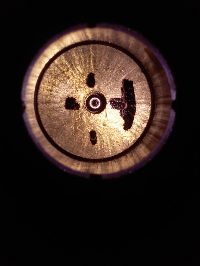
IMAGE 2: Front angle showing how previous marks correlate to further markings made. The only thing of importance here is the "T" shaped mark and the line it correlates with on the side of the host.
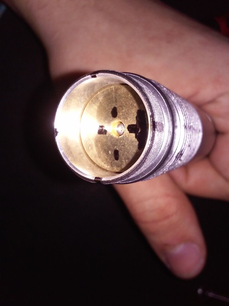
IMAGE 3: Side of laser showing two of the 90 degree division lines as well as further division marks (at 1/3rds intervals between the relevant 90 degree division marks.) to lay out the spot to drill the hole. The top line is the line that aligns with the "T" shaped mark in the first and second images while the other long line is the one that lines up with the bottom mark in image 1.
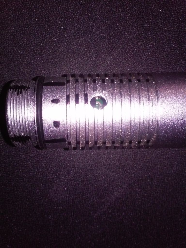
IMAGE 4: Image through the drilled hole showing the best position of the potentiometer for my unit. Anything past this point did not result in further output but did contribute to minor heat output as well as noticeable red-shifting.
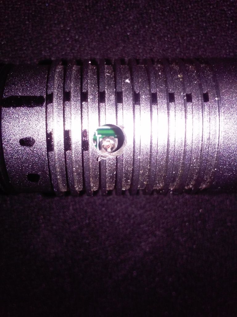
IMAGE 5: Proof of life for those into that kind of thing.
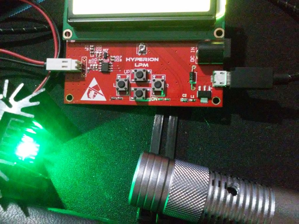
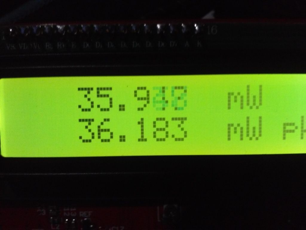
IMAGE 6: An image of the readout on my power meter.
Best of luck to anyone brave enough to attempt this.
That aside, this is a short guide on where to drill into these laserlands 520nm units to access the potentiometer for those that have the newer thread-locked units.
I recommended to laserlands that they should tread-lock the center section of the laser as with my unit, this center section will unscrew easier than the tailcap and could have lead to damaged units. Of course this was before I realized that the power of these little units could be increased considerably and of course they took my suggestion into account on the newer units.
This process took me half an hour to complete going very slowly with a sharp drill bit. One slip up drilling into these could very well ruin the unit completely so only attempt if extremely confident in your skills relating to the usage of power tools. You also have to be very careful to avoid getting any metal shavings in the unit while making the hole.
Only adjust the exposed potentiometer with the laser turned OFF as an electrical connection can be made between the case of the laser and the wiper on the potentiometer effectively bypassing it completely.
IMAGE 1: Front of laser showing facet and marks oriented every 90 degrees accordingly. "T" shape mark is the main one to worry about along with the marking at the bottom. The other two markings were only used as visual aids for making the bottom mark.
IMAGE 2: Front angle showing how previous marks correlate to further markings made. The only thing of importance here is the "T" shaped mark and the line it correlates with on the side of the host.
IMAGE 3: Side of laser showing two of the 90 degree division lines as well as further division marks (at 1/3rds intervals between the relevant 90 degree division marks.) to lay out the spot to drill the hole. The top line is the line that aligns with the "T" shaped mark in the first and second images while the other long line is the one that lines up with the bottom mark in image 1.
IMAGE 4: Image through the drilled hole showing the best position of the potentiometer for my unit. Anything past this point did not result in further output but did contribute to minor heat output as well as noticeable red-shifting.
IMAGE 5: Proof of life for those into that kind of thing.
IMAGE 6: An image of the readout on my power meter.
Best of luck to anyone brave enough to attempt this.
Last edited:


