Welcome to Laser Pointer Forums - discuss green laser pointers, blue laser pointers, and all types of lasers

How to Register on LPF | LPF Donations

laser driver help

Joined
Dec 26, 2008
Messages
42
Points
0
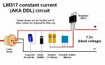
i read the laser driver tutorial, but before i start it, i need to know one thing as im a little confused, is the diagram in the tutorial using conventional system(inverted + and -) or electron flow system of showing it, and if it is using the electron flow, the why would the negative lead go directly to the diode as that where the charge comes out of, wouldn't it just fry it?

this is the driver tut im talking about... /forums/YaBB.pl?num=1185701612


I think it's safe to say the DDL driver (if built properly) will not fry the diode
 
I personally am not sure what you are asking, all I will say is that there must be thousands of these drivers knocking around that have been built by following that tiutorial and they work.

Regards rog8811

[edit]Same circuit different drawing style below.[/edit]
 

Attachments

  • LM317_components01_008.jpg
    LM317_components01_008.jpg
    102.2 KB · Views: 104
i mean, where it says - to battery + to battery, is it saying + as in where battery has more electrons, or the actual + lead on the battery, and if you can explain to me why the negative lead would go into the diode first, and then come into the output and adjustment side of the LM317 the going back into the battery from the input lead( is the input lead meant to go into the battery, not get voltage into the batterY?), i tought electron flow went from - to positive, am i getting something mixed up?

sorry if i am causing confusion, i just like to understand the circuit before i build it :P
 
I mean, where it says - to battery + to battery, is it saying + as in where battery has more electrons,
The drawing was for somthing else but it may suffice, the wires going out of the drawing to the left go to the LD. as you can see the input to the regulator comes from the end of the battery marked +, the end with the raised contact
wirebats01.jpg


If this is not answering your question I will leave it to someone else to try. :-/

Regards rog8811
 
Reaver789 said:
ok, but does the schematic use conventional flow method, or electron flow method?

The schematic shows standard common electrical connections as identified in the data sheets of said
components..
By your questions it seems that you have not yet built any type of electronic circuit....
A basic understanding of electrical components and circuitry would be an asset... :)


Jerry
 
i have done small stuff, but nothing with voltage regulators before so thats why i was confused...
i usually just mod circuits.

i am currently reading a 500 page book on how to build DC circuits, and i know ohms law, the way current flows, how to make current transformers, and i have an intermediate understanding of basic components( capacitors, resistors, pots, diodes) i just never dealt with voltage regulators, i usually just used resistors to limit the amperage, or capacitors for voltage drops....

current is uniform across a circuit, i do know that , but i just wanted to make sure, since i usually use resitors instead of voltage regs, i put the device which im trying to limit the current to, after the limiters, resistors capacitors.

edit: wooops lol, i just figured out its a positive voltage regulator... im stupid :P


Back
Top