- Joined
- Jan 27, 2014
- Messages
- 47
- Points
- 8
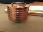
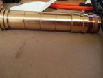
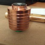
So, to begin, I am using ElectricPlasma's Bronze and Copper Host. I plan on putting an NDG7475 in it, and am using the AWP18650 batteries.
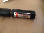
Upon first trying it out, I found that the batteries were larger than 18650s with no protection, and did not fit into the host nicely.
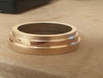
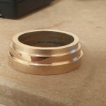
Thus, I sent it back to EP and he was so kind as to machine a new piece to go on the end so that the batteries would fit.
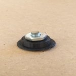
In addition, I messed up the initial contact board and tore the positive lead from the X-Drive. He was also willing to resolder that connection and make a new contact board.
Having received the laser host yesterday, I was quite excited to finally put it back together, after having practiced with epoxy to ensure that I don't repeat my past mistake with the contact board.
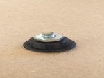
So I pressed the module into the heatsink, and then hooked the red lead into the nut and bolt of the contact board,
carefully and thinly coating the surface of the nut and bolt assembly with epoxy in hopes of preventing a short.
After that, I used the pinch method as shown to me by EP and BobMc, wrapping the black lead around the base of the contact board, making sure it doesn't touch the bolt or red wire.
And then I placed the board into the heatsink. From there, I got my batteries and some conductive magnetic spacers so the batteries would fit perfectly into the host.
Excited, I put them together without applying adhesive to the heatsink in fear that something would go wrong and I would have to pull it apart.
Despite fitting perfectly, I was able to see the green light for about a split second before it turned off.
I am hoping the diode has not been damaged, as I have been able to reproduce this incident a few times now. I'm not really sure I was able to do so, but I think that the diode still works, since it did all the times before.
So now I am here, wondering, where did I mess up and make an improper connection for this to happen? I've tried searching the forum, but I've been unable to find another incident like this. Perhaps I just missed it. Sorry for the wall of text, pics coming soon. Thanks everyone.


