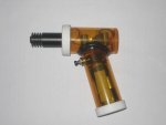
Here is my build and circuit schematic. Some may object to the form of the laser.
I used two pill boxes to create the case. I'm using 4 AAA batteries for power in the handle, and the current regulator is in the body. The circuit ramps the current linearly to its final value in just over 100 ms. The 470uf capacitor in parallel with the 2n2222A transistor sets the current rise ramp rate (the larger the capacitance the slower the ramp rate). The other 470uF controls the ramp rise rate slightly, but mostly provides energy storage to ramp the current down when the switch is opened (I think the current reaches zero in about 5ms). The concept of ramping the current to the laser is to reduced the thermal stress on energization and de-energization. The circuit will also ramp the current up from essentially zero due to switch bounce.
The circuit will regulate 420mA down to about 3.9-4.0 volts with a LOC red laser diode. Below this voltage, the current drops off. Select Rx so that the parallel combination of Rx and the potentiometer will give you the adjustment for the current you want [approximately 0.7 / (parallel resistance) = I reg]. Power dissipation for the 3055 is approximately Ireg x (Vsupply - Vld - 0.7).
You can use the PNP version of this circuit is you want to use a metal case and a negative ground.


