Welcome to Laser Pointer Forums - discuss green laser pointers, blue laser pointers, and all types of lasers

LPF Donation via Stripe | LPF Donation - Other Methods

Links below open in new window

ArcticMyst Security by Avery

how to measure mA with this multimeter?

tomi77

0
Joined
Oct 7, 2008
Messages
13
Points
0
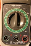
i saw same kind of question with a photo few pages back, but this meter has a slight difference to that other i think.
so i want to be sure how to measure mA with this.
should i put black to the COM, red to the red circle place ofcourse. turn the pot to Vac 200?
thanks
tomi
 

Attachments

  • laserforum.jpg
    laserforum.jpg
    246.8 KB · Views: 532


Joined
Oct 17, 2008
Messages
47
Points
6
If you're measuring up to 200mA (no more or else you'll blow the internal fuse) then switch it to Adc 200m and put the black lead in COM, and the red lead in the red socket.

Any more than 200mA and switch it to Adc 10A and put the red lead into the green socket.
 

tomi77

0
Joined
Oct 7, 2008
Messages
13
Points
0
thanks for answering.
i tried that  -switch it to Adc 200m and put the black lead in COM, and the red lead in the red socket-
, but nothing appeared to the screen.
only when i turned to Vac 200 there was something like "21".
i forgot to mention that i have a driver witch should be setted to 38mA.
my ps3 5-pin diode was so very dim that i wanted to make sure that the mA could be the promised 38mA or near.. i know it is should be dim but that dim..
is it ok to try to measure from these points?
 

Attachments

  • laserforum2.jpg
    laserforum2.jpg
    167.4 KB · Views: 522
Joined
Oct 17, 2008
Messages
47
Points
6
At the moment you will be measuring voltage.
To measure the current you need to connect the multimeter in series by putting one probe on a laser diode pin, and the other where you would connect that pin to on the driver board.

Edit: I was wrong, apologies :(
 
Joined
Apr 29, 2008
Messages
1,562
Points
48
No, you need a load. Connect the load (which can consist of 3 diodes in series, or an LED) to the driver and place the multimeter in series from the battery negative to driver negative or same with positive. A more recommended way (as the previous one can be a little inaccurate) is to place a 1-Ohm resistor in series with the driver, and measure the voltage from one side of the resistor to the other side.
Edit: Reading the post above, DO NOT PLACE THE MULTIMETER IN SERIES WITH THE DIODE. ONE SMALL DISCONNECT AND RECONNECT WILL CHARGE AND DISCHARGE THE CAPACITOR, THUS KILLING THE DIODE. When the diode is powered, make sure that it is soldered at all times. With the above method, you want to use a test load.
 
Joined
Feb 18, 2008
Messages
733
Points
18
12dstring said:
If you're measuring up to 200mA (no more or else you'll blow the internal fuse) then switch it to Adc 200m and put the black lead in COM, and the red lead in the red socket.

Any more than 200mA and switch it to Adc 10A and put the red lead into the green socket.

My meter gives me a false reading on the ma's setting so I usually use the amps setting. :cool:

--hydro15


Top