Welcome to Laser Pointer Forums - discuss green laser pointers, blue laser pointers, and all types of lasers

Buy Site Supporter Role (remove some ads) | LPF Donations

Links below open in new window

FrozenGate by Avery

How about a Homemade Laser Power Meter?

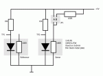
I have rigged a little setup with the thermal sensing idea - see picture for schematic.

This is just a proof of principe with some components i had around here, but it does demonstrate that it works, but with severe limitations.

The main problem is that the thermal mass of the sensor is so large it takes forever to get a stable readout - count on a minute or so. Looking at the schematic, you notice a resistor on the sensor plate. This is used to 'calibrate' the unit to some degree, as heating the sensor using the resistor does the same thing as heating it with a laser. Measuring between TP1 and TP2 using a multimeter, i got:

No laser, no jumper (i.e. zero) ~ -1.5 mV (due to tolerances in diodes and resitors)
JP1 position A, 5V/50mA=250mW: ~52mV.
JP2 position B 2.5v/25mA=63mW: ~ 12.9mV

According to the datasheet for the diode, it should result in about 2 mV/K response to heating up, which means 52mV ~ 26K temperature rise, or about 100 K/W for the whole sensor (sounds reasonable).

Notice that the schematic has 2 identical sensors, one exposed to the laser, one in the dark as reference. The reference sensor could be used in the future for better measurements, but for this series it could just have been any 1n4148 diode in the circuit.
 

Attachments

  • laserpower.gif
    laserpower.gif
    9.3 KB · Views: 1,472


I've taken some laser measurements with it as well:

DX200 red, ~36mV (~174 mW)
DX30mW/CR2 ~ 9mV (~47 mW)
KD30mW/CR2 (bit bad), ~ 4mV (~23mW)

... powers calculated with 4.7 mW/V, compensated for -1 mV offset

It seems to measure a little bit more than it should, but all of this was built with crude components like 5% tolerance resistors, and using 5 volts from a 78L05 voltage regulator.

Still, i think its a proof of principle and major problems could be reduced with better construction and SMD components on the sensors to reduce their thermal capacity. Also, it needs a good differential amplifier instead of just jabbing a multimeter between the sensors.
 
Benm said:
I have rigged a little setup with the thermal sensing idea - see picture for schematic.

This is just a proof of principe with some components i had around here, but it does demonstrate that it works, but with severe limitations.

The main problem is that the thermal mass of the sensor is so large it takes forever to get a stable readout - count on a minute or so. Looking at the schematic, you notice a resistor on the sensor plate. This is used to 'calibrate' the unit to some degree, as heating the sensor using the resistor does the same thing as heating it with a laser. Measuring between TP1 and TP2 using a multimeter, i got:

No laser, no jumper (i.e. zero) ~ -1.5 mV (due to tolerances in diodes and resitors)
JP1 position A, 5V/50mA=250mW: ~52mV.
JP2 position B 2.5v/25mA=63mW: ~ 12.9mV

According to the datasheet for the diode, it should result in about 2 mV/K response to heating up, which means 52mV ~ 26K temperature rise, or about 100 K/W for the whole sensor (sounds reasonable).

Notice that the schematic has 2 identical sensors, one exposed to the laser, one in the dark as reference. The reference sensor could be used in the future for better measurements, but for this series it could just have been any 1n4148 diode in the circuit.

Nice little circuit... :)

Just a thought... I've used the 1N914 and the 1N4148 glass diodes in some other non-LPM
circuits... and have noticed that they act a little like PIN diodes... they produce a voltage...
in the presence of a light source :-?
 
All pn / np semiconductor junctions generate a voltage when exposed to light.

In order to use a glass diode as temperature sensor you would need to isolate it from the light.

The 1N4002 did produce roughly 280mV when irradiated with 80-100mw/cm2 at 405nm, so the photo voltage is substantial and needs to be considered, as lasersbee suggested.
 
In my experimental setup, the sensing diodes are at the opposite end of a metal plate from the laser source, and hence receive no direct light from the laser at all - measurements are purely thermal.

Directly irradiating a black-plastic diode such as a 1n400x series is not an option really, as focussed powerful lasers will readily melt/burn the casing.

All in all the results from my quick junkbox setup are a positive surprise, and i do have some ideas on greatly improving the configuration. The response time problem is inherit to the type of sensor and cannot be remedied much, but other aspects can be improved...

10% accurate power measurement for stable lasers in the 10-1000mW range seems quite feasible at this point. This type of sensor will however never be able to read the peak output of a dpss laser, nor replace any real power meter in terms of accuracy or reliability.

On the other hand, i think many people on this forum would be interested in a system for rough, ballpark, power measurements that only requires a few bucks in parts and some handywork.
 
Benm said:
In my experimental setup, the sensing diodes are at the opposite end of a metal plate from the laser source, and hence receive no direct light from the laser at all - measurements are purely thermal.

Directly irradiating a black-plastic diode such as a 1n400x series is not an option really, as focussed powerful lasers will readily melt/burn the casing.

All in all the results from my quick junkbox setup are a positive surprise, and i do have some ideas on greatly improving the configuration. The response time problem is inherit to the type of sensor and cannot be remedied much, but other aspects can be improved...

10% accurate power measurement for stable lasers in the 10-1000mW range seems quite feasible at this point. This type of sensor will however never be able to read the peak output of a dpss laser, nor replace any real power meter in terms of accuracy or reliability.

On the other hand, i think many people on this forum would be interested in a system for rough, ballpark, power measurements that only requires a few bucks in parts and some handywork.

My mention of the glass diode light sensitivity problem was not to negate your circuit... it was merely to
point out an issue we had with glass diodes... so that you could remedy that characteristic if need be.

In our non-laser project we simply put black heat-shrink over the diode... which solved our light
issue with these types of glass diode.

As you say... even at 10% accuracy... if your circuit  can be built by any member for a few dollars...
it is surely a plus... 8-)

Jerry
 
It's good to point out.. in the current rig the diodes are still exposed to some ambient light that might throw off measurements to some degree, altough they're both in equal conditions compensating that a bit. For the next setup i'll have them dark to make sure.

I figure the main feature for home builders will be the resistor-heated thermal calibration, which sort of allows course measurements without any calibration equipment, known-good meter or reference laser.

What kind of sensor are you using in the 1 watt laserbee meter, if i may ask?
 
Benm said:
It's good to point out.. in the current rig the diodes are still exposed to some ambient light that might throw off measurements to some degree, altough they're both in equal conditions compensating that a bit. For the next setup i'll have them dark to make sure.

I figure the main feature for home builders will be the resistor-heated thermal calibration, which sort of allows course measurements without any calibration equipment, known-good meter or reference laser.

What kind of sensor are you using in the 1 watt laserbee meter, if i may ask?

We are using a Peltier cell in the Seebeck Effect mode which is then called a Thermopile....

Here is a post of a response to a member that absolutely refused to understand the difference
between a Thermopile and a thermoelectric cooler...

http://www.laserpointerforums.com/forums/YaBB.pl?num=1225241169/42#42

Jerry
 
The operating principe is fundamentally the same, only in reverse.

However, the practical construction is completely different, because of the different design goals. For a thermoelectric heatpump, you would like to move as much heat as possible with as little voltage drop as possible to make it efficient. When used as a sensor, you want as much voltage per unit of heat transported to make it sensitive.

The design goal is to measure a thermal flow as accurately as possible - i'm sure your sensors do great job at that, and a themoelectric cooler would not, altough it would work in principle.

Measuring temperature diferential using diodes or other temperature (not heat flow) sensors is a more crude approach, and only reliable if the thermal resistance from laser target to ambient is known or can be determined at the spot.


Back
Top