- Joined
- Apr 23, 2011
- Messages
- 177
- Points
- 28
So my great nephew has a Switch Lite that stopped charging, upon taking it apart I found the charge port solid but it's pins bent back in.
Repair isn't far from replacing price wise, and something I'm not willing to even try as it's soldered to the mainboard.
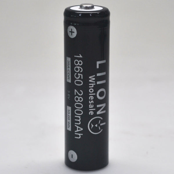
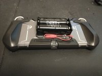
I came up with the idea of running an external battery and mounting two 18650s on the back so they just pop out for charging. Plus two in parallel will have more capacity than the internal battery.
So here's where I'm looking for some input, the battery has three wires, red +, black -, and gray TH.
After searching it would seem TH is thermistor, however, I get the same V reading across it and - as I do + & -.
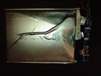
The battery has three tabs, -, +, and the third one is connected to the + tab via a LC77AY-1 thermal cutoff.
Edit: After a little further disassembly of the battery, there are only two tabs, the + was connected via the thermal cutoff.
I got two cell 18650 holders coming tomorrow and I'll test it out, firstly bypassing the thermal cutoff.
The two ways I was thinking of wiring up the external battery are connecting 2P directly to the + & - on the mainboard battery connector, or connecting the 2P to the board out of the battery.
Not sure it'll power on w/o V on the gray wire, haven't really tested yet but reusing the battery board seems easy but not sure about the TH. Plus I'll be using the OE battery connector, but even w/p using the board I'd clip the connector wires and reuse the connector.
Also not sure about the unit's cutoff so was thinking of getting protected cells.
Also also, I'd look into removing the charge port to ensure no shorts.
Any input appreciated, I'll be playing around with it through the week after work.
Thanks!

Last edited:


