Welcome to Laser Pointer Forums - discuss green laser pointers, blue laser pointers, and all types of lasers

LPF Donation via Stripe | LPF Donation - Other Methods

Links below open in new window

ArcticMyst Security by Avery

High Voltage (42V) Boost - Schematic Review?

rhd

0
Joined
Dec 7, 2010
Messages
8,475
Points
0
A long time ago Sinner built me a version of one of his hosts that takes 3S3P 18650s (ie, it takes 9x 18650s). It's a monster. I've decided to build it into a flashlight, rather than a laser, so I picked up a COB LED that requires 42V.

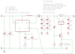
So - I needed a boost driver to boost 11.1V nominal voltage from the 18650s into 45V. Nothing existed that was small enough, so I set out to design my own.

The IC with the highest output current that was also capable of 42V output is the LT1370HV.
http://cds.linear.com/docs/en/datasheet/1370fs.pdf
It JUST makes the cut (its limit is 42V). It's a fairly straightforward IC.

Where things get a little challenging is in making a ZXCT1009 work at voltages above 20V. I have followed the application note here:
http://www.thierry-lequeu.fr/data/AN45-zetex.pdf
and am using a zener, transistor, and resistor, to increase the output voltage so that it will hopefully be able to handle sensing on a +42V line.

Would anyone mind taking a look at this schematic and telling me if I've missed anything? In particular, I'm not sure if my R1 value of 2.4k makes sense. They use 56k in the application note above, so I'm departing from that fairly significantly. The application note says to choose the value based on bias current of the zener, but the datasheet doesn't list the bias current. I just picked 10mA and calculated for R1 on that basis, but that's somewhat arbitrary.

attachment.php
 

Attachments

  • schem.png
    schem.png
    10.6 KB · Views: 1,110
Last edited:


Hiemal

0
Joined
Dec 27, 2011
Messages
1,443
Points
63
RHD, you can try to use the http://www.diodes.com/datasheets/ZXCT1107_10.pdf

which is basically the same exact thing as the ZXCT1009, except it costs less and can handle more input voltage. And, why three 100 uF caps in series?

That's going to 1/3th the total capacitance of them, and also add the ESR of each cap together. It might be better to use SMD electrolytics, or larger sized caps to get the voltage ratings you're trying to acquire without sacrificing ESR and capacitance.

Oh, and I've found that in pretty much every case of me designing and testing a driver, NEVER have caps after the resistor. Instead, put a cap between the + of the ZXCT and the iOUT pin, and it'll stabilize everything AND give a ridiculous soft start to boot proportional to the capacitance you use.

I also gave it some thought last night and another potential way to go about this would be to use a cap from VIN straight to the FB pin, since it would have the full battery voltage on it, and then slowly charge up giving a soft start effect too. This might actually be a better implementation.
 

Aleksa

0
Joined
Jan 21, 2014
Messages
118
Points
18
2.4k seems ok (depends on the current you want). You can use online zener diode calculator to double check.
 

rhd

0
Joined
Dec 7, 2010
Messages
8,475
Points
0
RHD, you can try to use the http://www.diodes.com/datasheets/ZXCT1107_10.pdf

which is basically the same exact thing as the ZXCT1009, except it costs less and can handle more input voltage. And, why three 100 uF caps in series?

That's going to 1/3th the total capacitance of them, and also add the ESR of each cap together. It might be better to use SMD electrolytics, or larger sized caps to get the voltage ratings you're trying to acquire without sacrificing ESR and capacitance.

Oh, and I've found that in pretty much every case of me designing and testing a driver, NEVER have caps after the resistor. Instead, put a cap between the + of the ZXCT and the iOUT pin, and it'll stabilize everything AND give a ridiculous soft start to boot proportional to the capacitance you use.

I also gave it some thought last night and another potential way to go about this would be to use a cap from VIN straight to the FB pin, since it would have the full battery voltage on it, and then slowly charge up giving a soft start effect too. This might actually be a better implementation.

I see that the ZXCT1107 can handle 36V.... I wonder conservative that is. IE, I wonder if it will still work at 42V? It sure looks like some funky stuff happens to that IC after the 36V mark (scroll down):
http://www.diodes.com/datasheets/ZXCT1107_10.pdf

Re: the caps, I'm using 3x in series because I happen to have a bunch of 16V and 25V rated 100uF caps. I don't have and 50V+ rated caps.
 
Joined
Dec 11, 2011
Messages
4,364
Points
83
I don't see any obvious errors or issues that aren't already pointed out.

Still though, I stand by my earlier recommendation for MAX1771. It can be made to operate at any voltage or current level desired (within the limit of silicon) and has relatively straightforward application (adjust voltage divider for Vsense, adjust current shunt for Isense, size inductor according to datasheet and basic formulae). The only downsides are that you need an external FET and FET drive, but that's just another chip or two transistors (totem) and the switch itself.
 
Joined
Aug 14, 2013
Messages
2,655
Points
63
How much current do you think this can
supply to the load? I have some 100W LEDs
that run at around 33.3V and 3A and have
been looking for something to drive them.
 
Last edited:

rhd

0
Joined
Dec 7, 2010
Messages
8,475
Points
0
I don't see any obvious errors or issues that aren't already pointed out.

Still though, I stand by my earlier recommendation for MAX1771. It can be made to operate at any voltage or current level desired (within the limit of silicon) and has relatively straightforward application (adjust voltage divider for Vsense, adjust current shunt for Isense, size inductor according to datasheet and basic formulae). The only downsides are that you need an external FET and FET drive, but that's just another chip or two transistors (totem) and the switch itself.

I already had a boost circuit based on the LT1370, so switching to the LT1370HV was easy. I'm a big fan of external FETs though, so I like the look of that IC

How much current do you think this can
supply to the load? I have some 100W LEDs
that run at around 33.3V and 3A and have
been looking for something to drive them.

Not very much. I was planning to parallel 6 of them at 500mA each.
 
Joined
Aug 14, 2013
Messages
2,655
Points
63
Well, it wouldn't work for me, since that is a buck driver, and I need to go from 11V to 42V. But for your application that might work well.

Yeah, it's a shame there aren't readily
available 50V cells. It wood bee a bit
dangerous, but make 100W flashlights much
easier.
 
Joined
May 8, 2015
Messages
1
Points
0
rhd, I cannot see any easily observable issues just by looking at it. But there are a few considerations when you’re going to be using a circuit with 42V potential difference, you’ll need to get capacitors of higher voltage rating, preferably 100V. Capacitors generally are 50V or 100V so that won’t be an issue. Also, the choice of the IC could be improved. I’m not sure if you chose the LT1370 because of availability or usability. Anyways, the circuits looks good.

electronic assembly
 
Last edited:

djQUAN

0
Joined
May 27, 2013
Messages
1,154
Points
63
The three capacitors in series might be a fire hazard. Ceramic caps won't share the voltages equally as you expect unless there are balancing resistors across each.

When one fails short due to impurities of the ceramic or due to micro cracks, the others start to see higher voltages. If they fail short too then it starts a chain reaction.

In my previous work, in critical high current supply lines (especially ones direct to batteries), we use two ceramic caps in series with each one able to handle the full supply voltage so incase one cap fails short, the other sees the full supply voltage and the circuit still works as it should.

Just a heads up.
 

Hiemal

0
Joined
Dec 27, 2011
Messages
1,443
Points
63
Then your best probable option would be to use SMT electrolytics, like these

Capacitors | Mouser

I already set up a filter for you. Anything above 100 uF 50 volts should show on the list.
 
Joined
Feb 5, 2009
Messages
198
Points
18
Since when are 50V rated capacitors inadequate for 42V operation?


well, that depends how stable that 42V is, since this is a switching converter, peak noise in the system must be taken into account as well. I'm assuming those caps are electrolytic as opposed to ceramic or tantalum just by the capacitance numbers. I would suggest using capacitors whose voltage rating is at least 2-3 times that of the expected voltage. For example, if you plan on decoupling or filtering a 5V bus, use a 10V or higher rated capacitor. I would recommend that Aluminum Electrolytic caps be derated to at least 50% if the capacitance is critical.

The voltage you're reading on the capacitor itself represents the "Rated DC voltage" and represents the maximum peak voltage including ripple voltage that may be applied continuously between the terminals and over the rated temperature range. Expect tolerance differences to present you with the short end of the stick.

Now, each type of capacitors will exhibit different tendencies, ceramic capacitors for example capacitance is inversely proportional to voltage. An ceramic cap could be rated at 10uF 6.3V but when applied 6.3V its actual capacitance may be down to only 2uF. Tantalum capacitors are prone to insulation breakdown at voltages only slightly over rated voltage, with a normal failure mode being a hard metallic short, smoke, and unhappy sounds. Electrolytics... tend to dry out if its used in hot environments. Seeing this is a boost circuit, im worried about temperature considerations. Have you considered Solid Aluminum Capacitors?
 
Last edited:


Top