Welcome to Laser Pointer Forums - discuss green laser pointers, blue laser pointers, and all types of lasers

LPF Donation via Stripe | LPF Donation - Other Methods

Links below open in new window

ArcticMyst Security by Avery

HeNe ballast resistor help

MattC

New member
Joined
Jul 13, 2019
Messages
6
Points
1
I need some help on my ballast resistor.

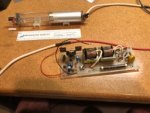
I bought a "1 mW" HeNe laser at the Dayton Hamvention electronics flea market around 1990 ! It had a tube and a power supply "kit" which consisted of a printed circuit board and components that you put together. Everything was fine, and, I was able to get it working back in the day. Also, it still works today ! But, for anything other than careful bench use, I really needed an enclosure for the power supply.

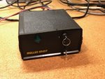
So I recently bought a surplus Melles Griot power supply, which fires the tube just fine. My only problem, the ballast resistor runs too hot and I have to shut it down after ~1 minute or so. I suspect the Melles Griot power supply is too powerful.

a) Can you confirm my thinking that the power supply is too powerful?
b) Can this be solved without discarding the Melles Griot power supply? It appears to be a nice little unit.

The tube is unmarked.

The instructions that originally came with the laser lists these additional specs:
- start voltage approx 8-10 kV
- run voltage approx 1-2 kV at 3 - 4.5 mA

..that's it.

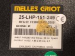
The Melles Griot power supply is a 25-LHP-151-249 and lists these specs on the label:
- output: 1.85 - 2.45 kVDC
- 6.5 mA

So. I don't remember the original power supply having a limited "on time". I seem to remember I could run it for 5+ minutes, then I'd get bored. With the new supply, it definitely gets hot!

The original ballast resistor was a 1W rated 121K resistor. With the Melles Griot supply, the resistor got hot enough to start to smoke the heat shrink tubing I had on the resistor. Next, I got a selection of Mouser 3W resistors. I ran at 150K and 200K and both times the resistors got hot enough to melt the small amount of solder I had tacked the hight voltage wire with.

I would have thought that the 200K resistor would have limited the current enough to reduce the power. I probably need to think through Ohm's law here!

Any thoughts?
 

Attachments

  • laser - 1.jpg
    laser - 1.jpg
    24.4 KB · Views: 9
  • laser - 2.jpg
    laser - 2.jpg
    28.3 KB · Views: 9
  • laser - 3.jpg
    laser - 3.jpg
    54.3 KB · Views: 6


Anthony P

Well-known member
Joined
Oct 7, 2018
Messages
529
Points
63
I tried unsuccessfully to find if that power supply had an adjustment pot inside. I can tell you that inserting a 1K resistor in series on the cathode side and reading voltage with a volt meter will tell you tube current. 1V = 1mA. This may help you find correct ballast. I know that is not much, but I hope it helps.
 

MattC

New member
Joined
Jul 13, 2019
Messages
6
Points
1
Thanks Tony! Great suggestion - I should have thought of that !

I suppose that once I learn the current with a given ballast, I can make sure that ballast resistor is rated to dissipate that amount of current. (P = I^2 * R).

I guess what I was wondering was, couldn't I just increase the ballast resistance to lower the current, thereby lowering the power that the resistor needs to dissipate? Maybe that's faulty reasoning, because, a higher resistance means that you have a bigger voltage drop over that resistor.... hmm.. I think I still need to research what's happening.

Of course, I suppose there must be a certain level of current required for the laser to even work.

I'll measure the current on the cathode side and then report back tomorrow!
 

MattC

New member
Joined
Jul 13, 2019
Messages
6
Points
1
Ok - that was quick. I wired in the 1k resistor on the cathode and measured a voltage drop of 6.45 V. Therefore, on a 1k resistor, that's 6.45 mA of current.

6.45 mA is the rating of the power supply, so I suppose it may have been maxed out?

This was with 200K ballast resistor on the anode side. This suggests the power dissipated on the ballast as 8.45 W ! (I^2 * R).

whoa. that's too high.

I'm now tempted to hook up the original power supply to see what's going on with that.
 
Joined
Sep 20, 2013
Messages
17,424
Points
113
You may be able to reduce the current in the MG supply if it has an adjustment for that. Otherwise you cannot use it without over driving your tube. It was likely made for a higher power tube of around 5 mW.
 
Joined
Sep 12, 2007
Messages
9,399
Points
113
I suspect you could shunt 2mA away from the tube by putting a 10x series array of standard 100K resistors in parallel with the tube, which is equivalent to a >2kV 1M 4W resistor. It's a waste of power, but it is way cheaper than buying a new PSU.
 

MattC

New member
Joined
Jul 13, 2019
Messages
6
Points
1
Ok - I've made some progress! I ended up buying a high voltage probe for my multimeter. I installed a 120K / 3W ballast resistor right before the anode, then the tube, then back to the Melles Griot power supply.

I put the multimeter ground clip on the tube's cathode connection (which is going straight back to the power supply) and measure the voltage before and after the ballast resistor.

The voltage before the ballast was 1080V, and between the ballast and tube was 665V. So, a 415V drop across the resistor. This means 3.45 mA of current, and 1.43 W.

Hmm.... this is not bad at all ! Again, the paper that came with the power supply and tube said the run voltage was 1-2 kV and current between 3 - 4.5 mA. It would seem that this is acceptable?

Now, my only concern is that the ballast resistor gets....HOT! Using an infrared thermometer, at an ambient temperature of 70F, I recorded the temperature at various intervals:

30s ...... 117F
60s ...... 158F
90s ...... 155F (not sure what happened here)
120s ...... 192F
150s ...... 225F

This was pretty repeatable.

I checked the resistor's data sheet. It lists a thermal resistance (Rth) of 60 C / W. So at 1.5W, this suggests 194F + 70F = 264 F !!!! The resistor is rated with a maximum operating temperature of 482F (250C), so I guess that is okay? The datasheet didn't list a thermal time constant, so I'm not sure how long it'll take to get to 264F. I was getting in the ballpark after 2.5 minutes, I suppose I'd be there in 3-4 minutes. I should probably do that and see if the temperature stabilizes.


Ok, now for the questions. Is this acceptable? I personally think it's just too hot. I'd prefer to have something at 100-120F. It's not that I'm touching the thing, after all it has hundreds of volts across it. But, I'd like to insulate it next to the tube with heat shrink tubing.

I think I could achieve lower temperatures on the resistors by using smaller resistors in series? That is, instead of a single ballast resistor at 120K, I could use three 40K resistors. Each one would have a drop of 140V and therefore dissipate 0.48 W each.

In looking at other resistors, I found some that have a thermal coefficient of 80C / W, so using three would put them somewhere at 160F. Interestingly, it appears that not all manufacturers have a spec for thermal resistance, so I can't be sure how other resistors would perform with this level of power dissipation.

Anyway, from the experienced folks out there, what do your ballast resistors look like in terms of power dissipated, temperature, or physical configuration? Any thoughts about my idea to use multiple resistors in series? (I don't think I would go more than 3-4 resistors)

(maybe this is obvious, but I want to run this HeNe laser tube indefinitely, but realistically 1-2 hours continuously)

-Matt
 

MattC

New member
Joined
Jul 13, 2019
Messages
6
Points
1
Tonight I had a chance to run it for a while. I ran it for 16 minutes. The temperature of the single ballast resistor topped out at 303F !

It wasn't building much temperature, so I think that was steady state.

Measurements were taken with an Extech IR thermometer at a distance of about 6 inches. ( At a distance of about a foot, the temperature read 250F, but I think the field of view for the sensor was too broad.)

Everything was stable, but the resistor was pretty hot, for sure! I didn't scan the tube itself that much, but I did get a reading of 108F. This may have been from the lasing cavity itself.


Thanks mojo for posting that example of multiple resistors. I'm going to pattern my configuration after that. I've purchased a few resistors from Digi-Key, the TE Connectivity part number RR03J39KTB, a 3 watt with a thermal resistance of 65C / W. Since I'm running at just under 0.5W, I expect a 37.5C rise on a 22C ambient. This should be down to 140F or so.

That's about the best I could find from Mouser and Digi-Key.

I'm going to fashion a ceramic ring to go around the tube's HC and place the three resistors on the opposite side of the tube, using this ceramic ring as an insulator. Having the resistors adjacent to the ceramic on one side will impede some of the cooling, but it should stay far cooler than the 300F+ I was seeing with a single resistor.

I suppose this tube is really a lab device - there isn't a great way to enclose it and not really impede the cooling of the resistors. I don't want to investigate a forced air cooling design. If I really think about more effort, I should just get a laser head.
 

Anthony P

Well-known member
Joined
Oct 7, 2018
Messages
529
Points
63
What kind of experiments do you have in mind for the HeNe when you get operating reliably?

EDIT:
Well, shoot! It was my intention to give you a 155-A Spectra Physics HeNe. Testing today indicates that it is only putting out 0.265mW out of 0.95. I can tell you that after 3 hours of running both the ballast and tube topped out at 160F.
If I get really ambitious, I might try a helium soak.
 
Last edited:

MattC

New member
Joined
Jul 13, 2019
Messages
6
Points
1
Hello Anthony!

Experiments...well, honestly, I'm not sure I have an objective here!


Also, I have the old "Laser Listener" article from a very old "Radio Electronics" magazine. It used a laser reflected off a window to a rifle scope-aided phototransistor to pick up room sounds. I always though that was interesting.

Maybe interferometer type measurements.

Finding an acoustic modulator also would be interesting to me.

I've also looked at those eBay galvanometers and thought about simple laser shows at my home.

I've thought about trying a hologram - but I may need a little more power - I suspect I'm around 1mW.


These are all ideas right now. Actually, the very first thing I'm going to try is a Peltier cooler based laser power meter. I've come across a couple articles, so I've got a 15mm x 15mm module en route courtesy of eBay. I also have a can of spray carbon black. The one article I found used some surface mount resistors that can be used for calibration, which I thought was very clever.

-Matt


Top