Welcome to Laser Pointer Forums - discuss green laser pointers, blue laser pointers, and all types of lasers

Buy Site Supporter Role (remove some ads) | LPF Donations

Links below open in new window

FrozenGate by Avery

HELP about stock dilda V2 driver

Joined
Oct 21, 2008
Messages
100
Points
18
Hello guys,
My dilda v2 diode died , so i decided to upgrade it to blu-ray one, but i still think that the stock driver wich i desoldered is working ok.So i want to reuse it with new LCC diode pressed into aixiz module and using this driver.My question is where do i connect the diode positive and negative pins?I wont need the case pin because i am not going to host it.

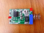
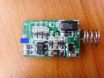
Here are some pics of the drivers both sides
ssl21442.jpg


ssl21444.jpg


And also where is the ground input?(somewhere near the spring)


1.-LCC is not bluray
2.-This driver is for red diodes only, bluray diodes need a higher input voltage.
3.-If you decide to use it for a new red diode, I highly recommend that you use a homemade LM317 driver. One diode has already dided with this driver, don't tempt the luck ;)
4.-Search for pictures on the forum about this laser insides, then you will know how was it originally connected.
5-.If you already know where to connect the wires but not the polarity, use a 1k resistor as load and a MM to know which is which :D
 
First of all i wam upgrading my laser to blu-ray with PHR-803T laser diode and a different driver for the blu-ray.I wanted to reuse the red driver that was originally in my laser and use it with LCC in aixiz module, but i dont know the output connetions of my red driver.

I hope that i was clear enough this time
Thanks
 
Oh, I understood now. Well, then forget about points 1 and 2 :)
 
Hello guys,
My dilda v2 diode died , so i decided to upgrade it to blu-ray one, but i still think that the stock driver wich i desoldered is working ok.So i want to reuse it with new LCC diode pressed into aixiz module and using this driver.My question is where do i connect the diode positive and negative pins?I wont need the case pin because i am not going to host it.

Here are some pics of the drivers both sides
ssl21442.jpg


ssl21444.jpg


And also where is the ground input?(somewhere near the spring)

on the first pic you can see GND it's - the spring blue, and VCC it's + red

before to connect your Diode laser use a DMM to know where is the - and + pin
 

Attachments

  • ssl21442.jpg
    ssl21442.jpg
    178.6 KB · Views: 244
  • ssl21444.jpg
    ssl21444.jpg
    186 KB · Views: 246
Last edited:
Uhm, sorry, was that an IR dilda ? ..... i can see from those pics that the connection point marked "GND" is connected to the spring ..... this is usual for IR, that are case positive ..... if so, you cannot use it for a red diode, that is usually case negative .....

Edit: for check this, take a multimeter and check if the not-connected pin near the one connected to the two 1,5 ohm resistors, is electrically connected to the pin on the other side (the one that go on C8), and if is electrically connected to the "VCC" pin near the spring ..... if yes, that is an IR driver for case positive diodes ..... the case pin go on that "apparently-not-connected" pin, the negative pin of the LD go on the pin connected to the two resistors R17/R18, and the photodiode/NC pin of the LD is connected on the opposite side of the PCB, on the track connected to C8 (is used just for mechanical support, anyway)
 
Last edited:
i was RED 200mw and it was case negative(negative towards tailcap) and that supposes that the spring is the positive input and GND suposes to be ground.But still there is a big mess in my head from the HIMNL9's post so please explain it more clear
 
i was RED 200mw and it was case negative(negative towards tailcap) and that supposes that the spring is the positive input and GND suposes to be ground.But still there is a big mess in my head from the HIMNL9's post so please explain it more clear

I was looking at the pics of the driver, that you have posted.

As you can see, the spring is connected with a track to the same point marked "GND" on the PCB ..... if also the pad where the case of the diode is soldered, is connected to the pad marked "VCC" (you need to check this with a multimeter), then that one is (or at least, it look as) a driver for case positive diodes ..... and, usually, case positive diodes are IR .....
 
You should have three pads in total, for soldering the diode's pins onto them,
Two of them are on one side, third is on the opossite ide of the PCB.

Just allign the diode to fit them ;)
As I said on Skype, when you look on the diode's pins so they form a right-pointing arrow, you have:
* positive
__* negative
* not used

Underscores used so I can space the stars away, forum does not let more than 2 spaces used in succession.

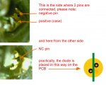
Wait, cause in the dilda that i have (IR) the LD is soldered in different way, and one of the pads (the one where you solder the case) is electrically connected to the single one on the other side (where is soldered the NC pin)

For this reason, i suggested to check if the "not connected pad" was electrically connected on the other one with a DMM

Wait, maybe a pic is better.

attachment.php


Is difficult to take a picture of this, cause it's inside the heatsink, but i think it can be seen the same, where the pins goes ..... and the pads on the opposite sides of the PCB, where are soldered the case pin and the NC pin, are electrically connected in my driver, and are the "VCC" of the driver through the diode case.
 

Attachments

  • diode-on-driver-dilda-IR.jpg
    diode-on-driver-dilda-IR.jpg
    104.8 KB · Views: 915
Wait, cause in the dilda that i have (IR) the LD is soldered in different way, and one of the pads (the one where you solder the case) is electrically connected to the single one on the other side (where is soldered the NC pin)

For this reason, i suggested to check if the "not connected pad" was electrically connected on the other one with a DMM

Wait, maybe a pic is better.


Is difficult to take a picture of this, cause it's inside the heatsink, but i think it can be seen the same, where the pins goes ..... and the pads on the opposite sides of the PCB, where are soldered the case pin and the NC pin, are electrically connected in my driver, and are the "VCC" of the driver through the diode case.
But nobody here is talking about IR dilda.

The dude has a busted red new style laser and wishes to turn it into a neat PHR build.

No IR anywhere.

The driver will be 'recycled' to provide power to new red diode in another host or something, and hence the question in this thread.
I do not have a red new style laser, but somebody who has could take some pics of the diode attached to the driver.

But in either case, you can only fit the diode in one possible way.
If it were up to me, I'd build another driver for another laser.... :)
 
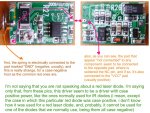
Eudaimonium, i'm not saying that you are talking about an IR dilda, i'm saying only that these pics are really strange ..... look at what i mean .....

attachment.php


I see only 2 possibilities, if that dilda was really a red and not an IR ..... first one, not too much possible, that it was using a very strange red laser diode, with positive on the case, instead negative ..... but in this case, there's no way for use this driver with any of the diodes that we normally use .....

Second possibility, they use the same PCB for IR and red drivers, with the same serigraphic prints, mounting some components "reversed" when they are used in red dilda, and in this case, are the words written on the PCB that have no sense, in this version ..... if so, this driver can be used for "common" red LDs, but is also for this reason that i have suggested him to check a pair of things with a multimeter, before connect it to a LD and power it (just for not risk to fry a good laser diode :p)

Looking better to the PCB, i see only one polarized component on that driver, as capacitors, and is the tantalium capacitor marked R26 (probably a typo) , the one near R23, with "220 T6" printed on it ..... so, the more easy way for check if this driver is a negative-case or positive-case one, imho, is to check with a multimeter if the spring is connected to the positive or to the negative of this capacitor (the positive is the side where you can see the white strip) ..... just use a DMM and check ..... if the spring is connected to the negative side of the capacitor, you know that you cannot use the driver for a normal red LD, and you need to build a new one, if instead the spring is connected to the positive side of the capacitor, you can use it for common red LD, just soldering the diode as i've drawed in the previous pic (cause in this case, the case and NC pins are soldered together to the negative line of the driver, that is marked erroneously as "VCC")


EDIT: and, if this second case is the right one and the PCB have the references printed wrong, i can auge to the builder of this PCB to trip and fall right into a big box of nails, for the sake of all the projects builders, LOL :p :crackup:
 

Attachments

  • dildadriverstrange.jpg
    dildadriverstrange.jpg
    265.8 KB · Views: 1,004
Last edited:
Nice writeup and everything, but bear in mind that the red laser did die prematurely.
Wrong driver used?
Possibly...
 
Nice writeup and everything, but bear in mind that the red laser did die prematurely.
Wrong driver used?
Possibly...

Uhm, yes, possible, but in this case, also the driver was fried (powering the IC reversed, it will be fried in seconds) ..... or, maybe, too high current regulation, or diode overdrived, or the driver circuit is wrong designed and produces spikes when turned on .....

I'm sorry, but having not the driver here for hook it on a scope, i cannot give any decent data, about this ..... maybe SeNNHeISeR have a scope, or know someone with a scope, for do some checking ? ..... just for not burn other diodes, before know what's the real cause of the premature dead of the first one ?
Speaking of which, I really gotta hunt down one oscilloscope myself... Perhaps in my school some surplus turns up or something :)

I was thinking that the driver was connectd on the diode in such way that it is powering it up nicely, but instabilities occur due to higher current and voltage needed to cover. Resulting in spikes, killing the precious diode.

Well, I will let him know my thoughts when I see him on skype next time.


Back
Top