Welcome to Laser Pointer Forums - discuss green laser pointers, blue laser pointers, and all types of lasers

LPF Donation via Stripe | LPF Donation - Other Methods

Links below open in new window

ArcticMyst Security by Avery

Hello from Tenn.


GSS

0
Joined
Apr 28, 2015
Messages
5,053
Points
113
Seth, that was mine you bought..
Just so everyone knows it's a 532 that was said to be 50mw and modded by someone named "Tony at Federation Phaser" I had it bought before I joined the forum.
Now the bottom handle holds 2 AAA's so he can use a 10440 and a spacer.
I never opened it and had no clue it was a separate driver. It was also modded with a option of a blue LED or the green 532 with a side switch.
The laser and LED also flashes to mimic the different sounds it makes, no continous laser. It's wired into the sound card which also ran the original low light red LED and everything ran on 3 button tops in the mini P1 phaser up top that snaps in.
The main body had no power source as the main body trigger hit a plunger in the button top battery P1 up top.
Now it uses the 2 AAA's in the main body handle for the 532 and the blue LED and still using the button battery up top for the sound.
These are very tight and a little complex inside.
Seth are you trying to pot mod it? Can you send some pic's to see if some higher power Fasttech's might work. They have them for around $5 in 2 different sizes. You can push them to at least 80mw on average..
 

Ceefuhs

New member
Joined
Sep 24, 2018
Messages
11
Points
3
GSS, why hello!!!
What pictures would you like me to post. Would pot mod be adjusting the pot for more output with a stronger power source?

Thanks again to everyone for the greeting and the help!


Seth
 
Joined
Sep 20, 2013
Messages
17,252
Points
113
Pot modding is increasing the current to the diode by adjusting the pot. I normally do it with a LPM to see what kind of power it is putting out. Some do it by eyesight alone. I have done it with 532nm solid state lasers mostly as they are often set below the optimum power level. I do sink the driver output and module to make sure it doesn't blow the pump diode.
 

GSS

0
Joined
Apr 28, 2015
Messages
5,053
Points
113
Yeah I did a double take when I first saw you post:)
Was always curious how he modded it with the laser and blue LED out of the same emitter.
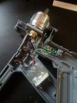
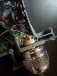
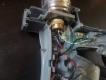
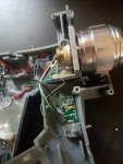
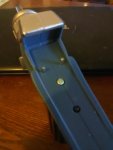
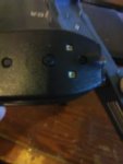
Can you post more and clearer pic's of the front, the back end of the nozzle showing the diode itself and how the blue LED fits in.
I assume you have all the parts out of the whole body. It's hard to explain how the whole assembly works in words also. Are you happy with the laser flashing instead of continuous lasing. Like I had mentioned he built it still wired into the sound settings. You can try to adjust the pot like Paul mentioned, but use a small jewlers type "ceramic" screw driver as its a positive groung DPSS system. Everything is exposed and it's easy to short it out. The only problem now is it looks like its apart and the trigger is out so you can't try to adjust it by running it and setting it to it's brightest or using a multi meter also..
If you can live without the blue LED a Fasttech module just might work well. Trying to wire it constant lasing might take some thinking.
I have one of these I built with a Fasttech 532 at module at 80mw and used a separate switch, it can be done but it takes some tinkering..
There are also available 150mw and 200mw modules from $25 to $50. If you ask Paul he might be able to set one up to it's best and most comfortable setting. Like he had mentioned heat is an issue and good driver sinking is important.
Before anything though post some better pic's, the more the better and there are so many knowledged members here to help.
I would try and link to post some pic's myself but I don't know how. I'm going to send you a PM ok..
 
Last edited:

GSS

0
Joined
Apr 28, 2015
Messages
5,053
Points
113
Seth, take a look at these.
https://www.fasttech.com/products/1088900

https://www.fasttech.com/products/1057303

For $5 a piece you have a easy potential for 80mW and maby more.. I recommend a few of both because they differ in size and one might fit better than the other. The smaller tipped one might also fit into the back of the AL nozzle.
Buy a few of each because if you are planning more builds they will come in handy. Setting them up for higher output you "might" accidently also kill one or two but being so cheap they are great and you will always have use for one like iv'e said..
When you post more pic's members can get a better idea.
Could be Chinese holiday's so shipping might be even slower. I might have a pointer with one of these that i'm willing to give you. It's also metered I think??
 
Last edited:

Ceefuhs

New member
Joined
Sep 24, 2018
Messages
11
Points
3
Here are some pics of the layout.
The module sticking out form the emitter / heat sink is 12 mm wide for reference.
The driver is 19mm x 12mm or close to that.
Toward the bottom of the first pic the is a SSD that uses the signal from the sound board/ button batteries to trigger the aaa for the laser diode if I am reading the layout properly.
 

Attachments

  • Driver.jpg
    Driver.jpg
    855.2 KB · Views: 7
  • Module 2.jpg
    Module 2.jpg
    774.5 KB · Views: 7
  • module.jpg
    module.jpg
    953.2 KB · Views: 5
  • overhead.jpg
    overhead.jpg
    899.6 KB · Views: 6
Last edited:

Ceefuhs

New member
Joined
Sep 24, 2018
Messages
11
Points
3
This is the unit actually assembled.
 

Attachments

  • Outside.jpg
    Outside.jpg
    431.7 KB · Views: 1
  • inputs to soundboard.jpg
    inputs to soundboard.jpg
    434.6 KB · Views: 1

GSS

0
Joined
Apr 28, 2015
Messages
5,053
Points
113
Much better look. Also see he's using a snap ring clip to hold the nozzle to plate.
The builder wasn't kidding when he warned me if I ever took it apart to be careful because he uses very thin wires. Looks like he removed the driver too because of room issue's. Lots of glue thats for sure but it's needed I guess especially in the handle area to support the added battery terminals. That's good though cause that doesn't need to be changed.
Were is the blue LED mounted or placed?
You would have to try to pot mod it with the battery's in. But he has it wired to 2 of the posts that come up that hit the P1 mini phaser up top.
Someone will have to chime in and see if you can bridge the 2 pins from each half of the body temporary to try.
Seth if you see the link of the first fasttech module I linked can you read it's dimentions and measure the inside of the phaser and estimate if it might fit with the fasttech module drivers still attached. I'm thinking the small tip diameter of that module might fit in the nozzle and slide in enough to maby have room?

Edit, the 2nd set of pic's show the 2 pins that come out of the main body that make contact with the 2 tabs on the bottom of little black P1 mini phaser. Behind the 2 pins is the top of the plunger that raises up and touches the rubber button on this mini phaser when pushing the trigger on the main body. The pins are wired to light the original low light red LED on the main body nozzle clear tip. The way it comes new and un modded is only the little mini P1 has 3 button cells to run the red LED and the sound..
When he added the 532 he used the handle to add 2 AAA's to run it plus a bonus blue LED. The sound is still powered by the button tops in the mini P1. The laser is wired also or spliced in to the sound card?? and flashes on and off the way the original red LED did.
Seth seems to be happy with the flashing though. If I remember, also I think the sound didn't work unless there were the 2 AAA's in the handle for the laser even with the button tops up top in the P1.
 
Last edited:
Joined
Sep 20, 2013
Messages
17,252
Points
113
It only now occurred to me that the builder of this laser might have used the driver for the LED to drive the laser diode. If that is the case, it is a disaster waiting to happen. If not, then I would still add a heat sink to the driver output transistor before pot modding this laser.
 

GSS

0
Joined
Apr 28, 2015
Messages
5,053
Points
113
Paul it's hard to explain how this laser works but of course easy when it's in hand.
I think you got the jist of it and how he modded and wired it. I can't make out the back of the 532 diode just by the pic's. You think he would taken off the original 532 driver and use the same one as the blue LED, which i'm not sure were it's placed but it does light up the akrylic tip.
Also don't have the knowledge to understand why the sound won't work even with the button tops in the P1 without the battery's in the handle for the laser. All its electronics and sound board are in the little P1 mini phaser up top.
 
Last edited:
Joined
Sep 20, 2013
Messages
17,252
Points
113
Yeah, I would have to see a schematic or have the host in hand to be able to answer questions about the sound, LED driver and such. The photos don't give me enough information about how these are wired to know exactly what is taking place here.
 

Ceefuhs

New member
Joined
Sep 24, 2018
Messages
11
Points
3
Sounds like it would be best for me to enjoy it as is and build my own if I want a more visible beam.

Thanks,
Seth
 

GSS

0
Joined
Apr 28, 2015
Messages
5,053
Points
113
Paul, just to add I took the momentary switch off one of my dead 532 fasttech modules and its the exact one, at least the same numbers and if you look he did bridge where the switch was.
 
Joined
Sep 20, 2013
Messages
17,252
Points
113
Yeah, I normally leave the switch in place and just add a short piece of wire to short across it. If you don't look closely enough you can miss it. I'm not a big fan of those tactile switches as they aren't rated to carry the current that the ones with a 1 watt pump diode use.
 
Joined
Jul 10, 2015
Messages
9,799
Points
113
Welcome to the forum Ceefuhs. :)

I haven't seen it said yet although I may have missed it, even a 50mw laser ( actually anything over 5mw ) can damage your eyes/retinas so remember to avoid reflections and wear safety glasses where appropriate.
 
  • Like
Reactions: GSS


Top