Welcome to Laser Pointer Forums - discuss green laser pointers, blue laser pointers, and all types of lasers

LPF Donation via Stripe | LPF Donation - Other Methods

Links below open in new window

ArcticMyst Security by Avery

Focusing my Laser

Joined
Mar 20, 2007
Messages
7
Points
0
Hi all,
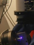
I hope someone here can advise me. I have recently bought a 405nm laser in order to pattern printed circuit boards. They are not flat PCBs, but spherical: copper-coated plastic spheres, with a layer of negative photoresist (where the light hits will end up as copper). They are mounted in a 5-axis milling machine, with the laser mounted in the tool holder. The machine moves the spheres around, drawing the tracks with the laser.

However, I am having some trouble properly focusing the laser to make nice sharp tracks. Can anyone help me? The trouble is not just getting a 0.2mm spot (which I can do) but totally cutting out all of the light around the spot. At the moment, the extra light is enough to blur the image. I have tried a mask, but even a 0.5mm mask causes diffraction!

Does anyone know how to focus a laser down to 0.2mm, leaving no extra light around the spot?

Many thanks

Hugo


S

SenKat

Guest
You will have to find a way to add a focusing optic on the end of the aperature of the laser you are using - some folks have modified their pointers on here to externaly focused units by sliding a small tube over the laser - and glued in the tube is a focusing optic....
 
Joined
Mar 20, 2007
Messages
7
Points
0
Hi SenKat,

thanks for the reply. Yes, I know I need to add optics onto the laser. The question is 'which optics?' Does anyone have any experience making a spot with no extra light outside the spot?

Many thanks

Hugo
 
S

SenKat

Guest
Can you post a picture of what you are working with ? That might free up some more ideas to come your way....It would help to have a close-up, clear picture of what to work with !
 
Joined
Mar 20, 2007
Messages
7
Points
0
Hi,

OK, here's a diagram of my current setup (rotated 90º - normally the laser is at the top).

Hugo
 

Attachments

  • Laser_Focusing.gif
    Laser_Focusing.gif
    4.5 KB · Views: 104
Joined
Mar 20, 2007
Messages
7
Points
0
And here's a photo, taken in near darkness with a very long exposure. You can see that the target PCB is rotating.
At the top of the image, you can see the bottom of the magnifying lens (darth-vader hat) and the white tube holding the laser.

Many thanks for any insight.

Hugo
 

Attachments

  • Lasering_PCB_01.jpg
    Lasering_PCB_01.jpg
    30.2 KB · Views: 116
S

SenKat

Guest
From the pics, I imagine the pinhole is there to knock out any extra or spare scatter that would be present after the initial lense.  If the 7x magnifier lense is already in place, perhaps a 25X or more  - with the same focal length would hit the spot ?  You could enlarge the pinhole (make a spare first !!!!) to let more of the lasing light through - and then add an aperature of some variety AFTER the 25x lense.  Just an idea....

BTW - what is the strength of that diode - and do you have any spares ?  ;D Also - with proper planning, would you be able/willing to produce a few circuit boards for a small fee ? Just checking ! It NEVER hurts to ask !
 
Joined
Mar 20, 2007
Messages
7
Points
0
I think I'm going to try buying some proper lenses. At the moment, the 7x lens I'm experimenting with is plastic, and probably the cause of some of my problems.

BTW - what is the strength of that diode - and do you have any spares ?

Hah! In my dreams ;D This bad boy cost us £8000. Nearly broke the bank. The reason I want to have such a long distance between the laser and the PCB is to stop the machine damaging the laser if something goes wrong. There are no spares. It's 60mW, 405nm.

Also - with proper planning, would you be able/willing to produce a few circuit boards for a small fee ? Just checking ! It NEVER hurts to ask !

It depends. You can't have any of the ones we are making now, because they are supposed to be secret. :-X Or do you mean custom ones? Also, it would take a lot of planning. The setup isn't too good at the moment. Firstly, the poor laser spot is causing the tracks to come out badly, and they need hours of hand finishing. Secondly, it's not perfectly aligned, meaning that some of the tracks come out in slightly the wrong place. Also you'd need software to calculate the G-Code to run on the machine. Maybe you have that already though.

Do you mean curved PCBs or flat ones? What would they be for?

Hugo
 
S

SenKat

Guest
Curved or flat - doesn't matter - actually, curved may fit nicer inside some tubes anyways ! I was just tossing around some ideas in my head - and being lazy, instead of making my own PCB's is always a nice choice ! In all acutallity, though - since you are all the way across the pond - it would most likely be way too expensive :(
 
Joined
Mar 20, 2007
Messages
7
Points
0
Well, the easiest way to make a cylindrical PCB would be to use flexible PCB, and glue it to a tube. And for flat ones, it's so cheap to get them manufactured, it's amazing.

Hugo
 
S

SenKat

Guest
Yeah - it's painstaking, and involved to make one yourself - but very rewarding, knowing YOU made it ! ::)


Top