Welcome to Laser Pointer Forums - discuss green laser pointers, blue laser pointers, and all types of lasers

Buy Site Supporter Role (remove some ads) | LPF Donations

Links below open in new window

ArcticMyst Security by Avery | Browser Hide by Avery

Focus help! (ofc XD)

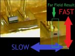
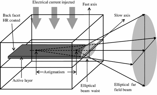
The fast axis is the one with the higher divergence. It starts out with a smaller diameter but diverges quicker, forming a line in the far field. The slow axis starts larger but has a lower divergence and thus forms the narrow side of the rectangle in the far field.

The slow axis is smaller in the far field because the divergence is significantly lower.

There's a reason it's called a cylinder pair. Not sure how you'd form a beam expander with one lens.


I see we're not quite on the same page.
The fast axis is vertical....
The reason I suggested slowing the slow axis was to square up the beam only (with no implication to make a beam expander). If not, the rectangular or bar shaped beam profile (spot) is maintained and gets bigger with distance. Slowing the fast axis still leaves a bar shape beam profile (spot). So the OP wants to get rid of the bar shape beam spot and slowing the slow axis is the way to do that.


Maybe this overview will help members understand the situation and technical circumstances with greater clarity.

The reason that correction of slow and fast axis divergence is uncommon in hand held portable lasers and is not part of ordinary laser pointer manufacturing/production is because they are designed to be as cheap/low cost as possible for pointing or demonstration, better beam quality does not matter/ is not necessary for any envisioned applications. There is little if any but a small niche market for something better and the nature of low cost mass produced laser diodes never designed or meant tor inclusion in handheld laser pointers which is way too small a market justify mass production of laser diodes, the market and purpose for laser diodes being generally commercial video projector manufacturers with the goal of making them at lowest cost possible at whatever quality and cost point the manufacturer wants to target for large scale distribution and sales.
Keep in mind the first relatively low cost laser diode pointer production were the Wicked Lasers Spyder III Arctic pointers made from Ca$$io projector diodes. Everything that came after was essentially a "me too" product to make $s in a growing demand for pointers fueled by clever marketing and videos on TY and so on. Their purpose in the real world was what? Create an interesting toy with a Star Wars light saber look to pop balloons and light matches and make a bright beam marketed to an enthusiastic base at a relatively affordable price compared to earlier iterations costing thousands of dollars using DPSS lasers and having better beam quality. Certainly, not to be laboratory quality research lasers.

Bottom line is $$$ and that " you can't make a silk purse out of a sow's ear" for the low disposable income level customer which the majority of the largest potential customer base with only X to spend are combined with that they have no real reason.need to own a laser of any kind to begin with.
A laser pointer was an affordable advanced curiosity/cool novelty thingy from the outset marketed by captuing the imagination of thousands of customers and potential customers as something new and different, "lightsaber" like, and also dangerous even better.
The market base for pointers, generally, just wants cheap and makes a visible light beam so....

The enthusiast and hobbyist laser market people can dress it up to make it look a bit better and have the $$$ to spend doing so and better quality optics for doing just that are available.

Better than pointer quality, better beam quality diode lasers with a divergence <1.5 mrad and even < 1 mrad are made, marketed, and sold as lower cost lab units at prices much higher than any pointers due to housing costs, optical components, adjustments /set-up needed, power supply, and testing costs necessary to produce same.
Examples are CNI's range d diode lasers --see: https://www.ultralasers.com/lasers-series.php?cat=42

"Broad area laser diodes (also called broad stripe or broad emitter laser diodes, single-emitter laser diodes, and high brightness diode lasers) are edge-emitting laser diodes where the emitting region at the front facet has the shape of a broad stripe, with dimensions of e.g. 1 μm × 100 μm. Due to the asymmetry of the emitter, the beam properties are also completely different for the two directions:
  • In the vertical (short) direction, the height (e.g. 1 μm) is small enough to obtain single-mode guidance and thus an essentially diffraction-limited beam quality with an M2 factor only slightly above 1. Because of the small aperture size, the beam divergence in this direction is relatively high, with a beam divergence half-angle of e.g. 370 mrad, corresponding to an FWHM angular range of 25°. Due to that fast divergence, this is called the fast axis direction.
  • In the long direction (slow axis direction), the stripe width may be e.g. 50, 100, 200 μm, or even larger, so that the light is distributed over many spatial modes in this direction. As a result, the beam divergence is much larger than for a diffraction-limited beam with that size, although still significantly smaller than for the fast axis direction. (Typical values are around 5–10° FWHM.) The beam quality in terms of focusability is reduced; M2 might be of the order of e.g. 20 for a 100-μm stripe. Furthermore, the beam profile may be multi-peaked in the horizontal direction, and the shape of the intensity pattern may depend on the injection current.
The wavefronts at the output facet are approximately plane in horizontal and vertical direction, but there can be some astigmatism, i.e., a slightly different focus position for the two directions."
"The strongly asymmetric beam profile and the large divergence in the “fast” direction requires special care, e.g. for properly collimating the output of a broad area laser. A common method is the use of a cylindrical “fast axis collimatorlens with high numerical aperture in close proximity to the diode facet. Such a lens collimates the beam in the fast axis direction, before the beam radius becomes too large. A second cylindrical lens at a larger distance may then be used for collimation in the slow axis direction. By choosing lenses with suitable focal lengths, a circular beam can be obtained, which however will have different divergence angles in the two directions due to the different beam quality values. "
The above from: https://www.rp-photonics.com/broad_area_laser_diodes.html

"Collimators for Single-emitter Laser Diodes"
"Asymmetric beams are typical for laser diodes."
"Single-emitter laser diodes usually exhibit substantially different divergence in two orthogonal directions. In typical cases, one has about 10° divergence (full width at half maximum) in the “slow” direction and ≈30° in the “fast” direction. On the other hand, the focus positions are often very close together (very small astigmatism) at least for so-called index-guided laser diodes, so that an ordinary lens (not a cylindrical one) placed at an appropriate distance to the laser diode output can simultaneously collimate light in both directions. Only, the beam radius in the two directions will be substantially different; it may for example be about three times larger in the “fast” direction.

In many cases, it is required to transform the beam profile into a circular one; this is often accomplished by applying an anamorphic prism pair, which may either be used separately or integrated into a laser diode collimator device. Alternatively, one may use two cylindrical lenses, each one having a focal length which is appropriate for obtaining the desired beam radius in its direction. Another technical option is a cylindrical microlens mounted with high precision close to the laser diode facet for transforming the beam into a circular one."

"Astigmatism makes it more difficult to produce a circular beam."
"For gain-guided laser diodes (typically those with higher output powers), there is the additional problem of astigmatism: the focus positions for the two directions do not exactly coincide. Although their distance is small compared with the length of the laser diode chip, it is substantial when comparing with the Rayleigh length. A consequence of that is that slightly different lens positions (distances to the output facet of the laser diode) would be required for perfect collimation in the two directions. Although an anamorphic prism pair can still be used for producing and approximately circular beam, the astigmatism cannot be corrected that way.
A pair of cylindrical lenses, which can be independently adjusted, can be a good solution.

Strictly speaking, the used cylindrical lenses often have acylindrical surfaces, i.e., some deviations from the cylindrical shape such as to minimize aberrations (see the article on aspheric optics)."
The above from: https://www.rp-photonics.com/laser_diode_collimators.html
 
Last edited:
I see we're not quite on the same page.
The fast axis is vertical....
The reason I suggested slowing the slow axis was to square up the beam only (with no implication to make a beam expander). If not, the rectangular or bar shaped beam profile (spot) is maintained and gets bigger with distance. Slowing the fast axis still leaves a bar shape beam profile (spot). So the OP wants to get rid of the bar shape beam spot and slowing the slow axis is the way to do that.


The fast axis is whichever axis is fast... Slowing the slow axis just makes the issue worse, if you want to square up the beam you'd want to increase the divergence on the slow axis. Slowing the fast axis creates a square beam instead of a bar.

Read the article I linked, it explains it all.
 
The fast axis is whichever axis is fast... Slowing the slow axis just makes the issue worse, if you want to square up the beam you'd want to increase the divergence on the slow axis. Slowing the fast axis creates a square beam instead of a bar.

Read the article I linked, it explains it all.
From the article.
In the vertical (short) direction, the height (e.g. 1 μm) is small enough to obtain single-mode guidance and thus an essentially diffraction-limited beam quality with an M2 factor only slightly above 1. Because of the small aperture size, the beam divergence in this direction is relatively high, with a beam divergence half-angle of e.g. 370 mrad, corresponding to an FWHM angular range of 25°. Due to that fast divergence, this is called the fast axis direction.
Typically diode lasers are mounted is such a way as to create a horizontal stripe. Therefore the fast (short) axis is vertical.
 
Last edited:
From the article. Typically diode lasers are mounted is such a way as to create a horizontal stripe. Therefore the fast (short) axis is vertical.

The orientation of the die is irrelevant here, and your earlier post is incorrect.
 
The orientation of the die is irrelevant here, and your earlier post is incorrect.
From the article you referenced, multi-mode diodes have a smaller opened area, in this case 1 um as opposed to a longer one (100 um), that they are also calling the slow axis. The fast axis, in this case, is 1 um. So, really the geometry of the die face is very relevant as the one that is making the line in the far field is the 100 um one. They are also calling this the slow axis. It is the one with an M2 factor of ~20 as opposed to the fast axis with an M2 of just over 1. The reason this fast axis is more divergent is the gap of 1 um. This holds true for single mode diodes, but in that case the fast axis IS the one that diverges in the far field as well. Multi-mode diodes with an emitter face 100 um long give a line, or bar, in the far field because of the emitter's geometry. The collimation lens gives you a representation of the emitter face unless acted on by other BE optics. That is why the slow axis appears to diverge faster than the actual fast axis.
 
The fast axis is vertical....

XzE0V.gif


This is so abjectly stupid I don't really know how to begin... Do you not understand lasers can be rotated? No, surely you know that. Do you not understand that the word FAST and VERTICAL have nothing in common? No, surely you know that. Do you not understand what an axis is? What can you possibly mean? I literally can't even parse your sentence.

the OP wants to get rid of the bar shape beam spot and slowing the slow axis is the way to do that.

What does "slowing the slow axis" even mean? Are you making things up or haphazardly repeating things you've read somewhere else? Are you suggesting reducing the divergence of the axis that already diverges slowly? That would mean even more of a line shape. Not only have you participated here over 12 years, you seem to be dreadfully confused on a relatively simple topic, which baffles me, since you're so adamant.

Since you're so keen on invoking Cunningham's Law today, I'd better play along.

A slight oversimplification is as follows:
1) a laser die output facet (especially a high power one) is not radially symmetrical.
2) Therefore the output beam is not symmetrical.
3) Therefore each axis has a different initial diameter.
4) As we know, divergence is inversely proportional to beam diameter, all-else-equal.
5) Therefore, since one axis is narrower, that axis diverges faster.
6) the axis that diverges faster is (surprise, surprise) called the fast axis.
7) Therefore, you must expand the fast axis diameter to narrow its divergence to bring it closer to that of the slow axis.
8) Alternatively, you may narrow the slow axis diameter to increase its divergence, but this is typically not preferable for obvious reasons.
 

Good diagram Red!
So, really the geometry of the die face is very relevant as the one that is making the line in the far field is the 100 um one. They are also calling this the slow axis.

Yes, the geometry is relevant but the orientation isn't. Diagram that Red posted is a really good representation for those who aren't getting it, or if you prefer text Cyparagon posted a good explanation too.
 
This is so abjectly stupid I don't really know how to begin... Do you not understand lasers can be rotated? No, surely you know that. Do you not understand that the word FAST and VERTICAL have nothing in common? No, surely you know that. Do you not understand what an axis is? What can you possibly mean? I literally can't even parse your sentence.


What does "slowing the slow axis" even mean? Are you making things up or haphazardly repeating things you've read somewhere else? Are you suggesting reducing the divergence of the axis that already diverges slowly? That would mean even more of a line shape. Not only have you participated here over 12 years, you seem to be dreadfully confused on a relatively simple topic, which baffles me, since you're so adamant.

Since you're so keen on invoking Cunningham's Law today, I'd better play along.

A slight oversimplification is as follows:
1) a laser die output facet (especially a high power one) is not radially symmetrical.
2) Therefore the output beam is not symmetrical.
3) Therefore each axis has a different initial diameter.
4) As we know, divergence is inversely proportional to beam diameter, all-else-equal.
5) Therefore, since one axis is narrower, that axis diverges faster.
6) the axis that diverges faster is (surprise, surprise) called the fast axis.
7) Therefore, you must expand the fast axis diameter to narrow its divergence to bring it closer to that of the slow axis.
8) Alternatively, you may narrow the slow axis diameter to increase its divergence, but this is typically not preferable for obvious reasons.


I was keeping simple. The goal of the OP is to reduce the length (bar shape) to something more dot like. Go read his 1st post (again). I originally wrote the easiest way would be to slow the slow axis. In slightly more technical terms to decrease the divergence of the slow axis creating a square or squarish beam.

In the post by Redcowboy the drawing shows the fast axis oriented vertically. The RP Photonics literature which I quoted describes the fast axis being vertical. Typically in the literature worldwide and in drawings that is how the fast and slow axis are presented. Am I really making stuff up? Perhaps I should have written the fast axis is orthogonal to the slow axis.
 
Last edited:
I was keeping simple. The goal of the OP is to reduce the length (bar shape) to something more dot like. Go read his 1st post (again). I originally wrote the easiest way would be to slow the slow axis. In slightly more technical terms to decrease the divergence of the slow axis creating a square or squarish beam.

In the post by Redcowboy the drawing shows the fast axis oriented vertically. The RP Photonics literature which I quoted describes the fast axis being vertical. Typically in the literature and in drawings that is how the fast and slow axis are presented. Am I really making stuff up? Perhaps I should have written the fast axis is orthogonal to the slow axis.


Don't you mean reduce the divergence of the fast axis like the 808nm c-mount diodes do with a single fused silica FAC lens ( Fast axis correction ) lens placed near the facet ?

It's still not practical for the OP but slowing the slow axis makes no sense at all.


299932_1_En_1_Fig1_HTML.gif


1328783663125


---edit---

On the RP Photonics page they say the narrow region is the fast axis and the wide region is the slow axis and that their pic ( Image 1 ) shows the emitters with the vertical being the fast axis, which are the narrow regions..........so in their ( Image 1 ) it is the vertical as they said, but that does not mean that every image and every reference everywhere worldwide must show the fast axis in the vertical orientation, it's just pertaining to their ( Image 1 )

diode_bar.png
 
Last edited:
I was keeping simple. The goal of the OP is to reduce the length (bar shape) to something more dot like. Go read his 1st post (again). I originally wrote the easiest way would be to slow the slow axis. In slightly more technical terms to decrease the divergence of the slow axis creating a square or squarish beam.

In the post by Redcowboy the drawing shows the fast axis oriented vertically. The RP Photonics literature which I quoted describes the fast axis being vertical. Typically in the literature worldwide and in drawings that is how the fast and slow axis are presented. Am I really making stuff up? Perhaps I should have written the fast axis is orthogonal to the slow axis.


In slightly more technical terms? It's not more technical when you're wrong. You can't make a square beam by further reducing the divergence of the slow axis. Period. End of discussion.
 
Reducing the slow axis only will just worsen the beam profile and make the fast axis 'appear' greater. Not sure what the confusion was all about, the axes are labelled based on divergence rate not orientation. It just happens that most diodes have a fast axis on the vertical plane. Doesn't mean the vertical plane is the fast axis.
 
It just happens that most diodes have a fast axis on the vertical plane. Doesn't mean the vertical plane is the fast axis.

They're typically cylindrical objects. Which end is the TOP? And when did we agree on it? This is like telling someone to eat a hot dog backwards.


Back
Top