ducatidragon916
New member
- Joined
- May 17, 2020
- Messages
- 20
- Points
- 3
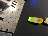
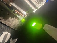
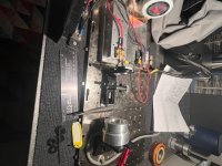
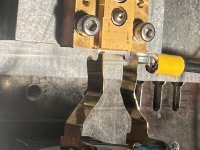
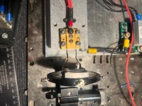
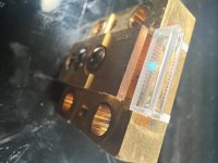
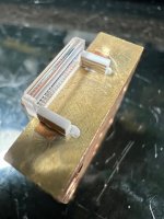
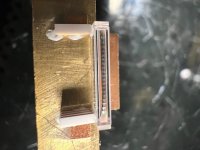
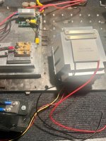
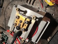
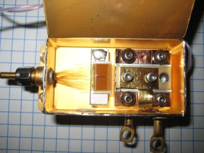
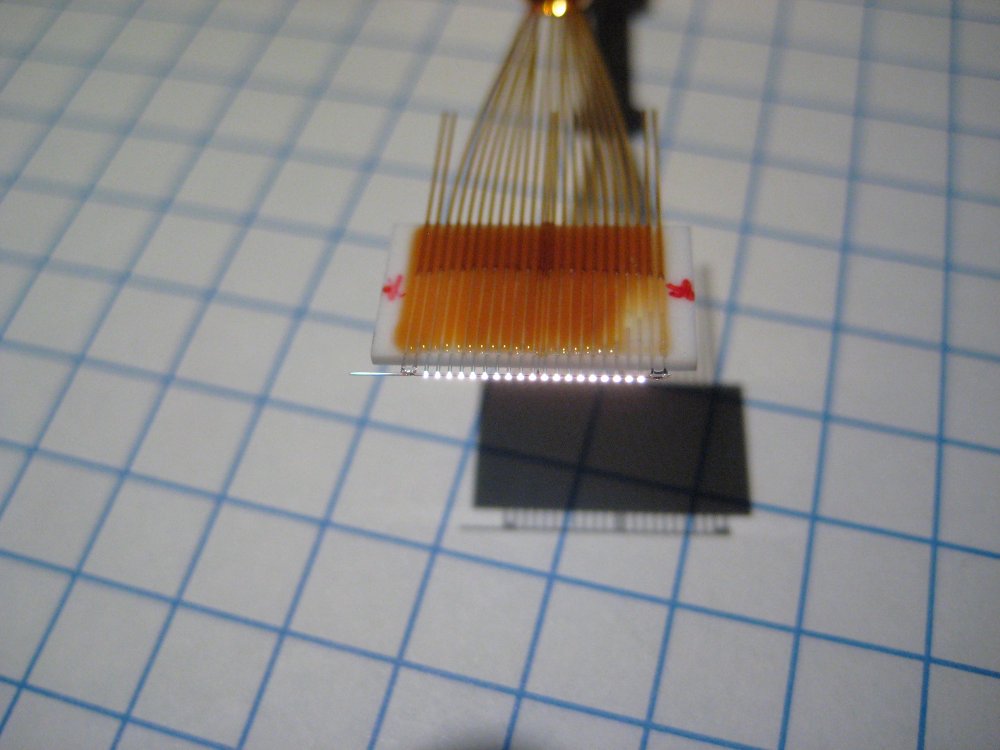
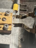
So I have had this laser unit CS- mount 975nm 600 um emitter. I was able to find a fac/sac lens combo to try my hand at fixturing this lens on the die. Standard package for the die is CS-975-040W-65. I was somewhat successful at attaching the lens with a jig setup as I will show at the end. I decided to add a TEC unit to help keep things cool. Now what is perplexing me is when I fire the laser up and observe with an ir image sensor, I notice the beam looking horizontal with intense lines in the center and degrading Intensities of lines on the left and on the right side of the beam. I am thinking I need an aspheric lens to set things straight etc so to speak.
Attachments
Last edited: