gillza
0
- Joined
- Jul 26, 2010
- Messages
- 583
- Points
- 28
I apologize for double post. But this is new information and I believe it justifies my breaking of the rules:
I got the calibrated LPM back on Saturday, and remeasured all my lasers. Justin also sent me a PM saying that the configuration of the TEC, Heatsink and coating layers resulted in a sensor that was able to measure his most powerfull ~3W 445nm laser (this one perhaps: http://laserpointerforums.com/f39/fs-2-8w-3w-peak-445nm-maglite-295-a-77438.html) after calibration. In addition he confirmed the measurements of his 635nm lasers.
I have initially wanted to use a smaller heatsink, but decided to use an existing CPU aluminum heatsink. The surface to which the TEC was glued (using Arctic Silver Epoxy) was sanded with the finest grade sandpaper I could find in Lowes. Cleaned with alcohol and the TEC was glued. I have used the press with rubber pads to push the TEC as close to the metal as I could and let it dry for several hours.
After that the heatsink and TEC were sprayed with multiple layers of above mentioned Rust-oleum spray letting individual coats dry off for a minute or so.
Then I connected the sensor to the wires from LPM and determined which wire is positive and which is negative (shined the laser, if the neg values grow, switch the wires around). Soldered everything back together and done.
Below are some of the pictures:
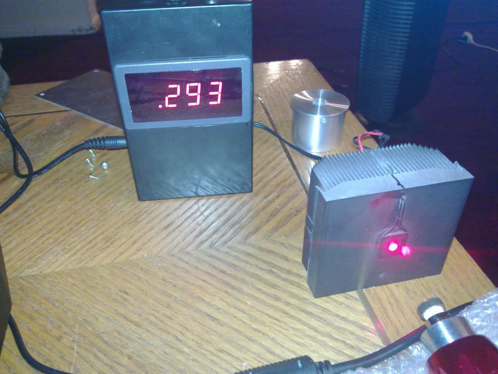
Red LPC-815 650nm Diode running at 450mA, aixiz glass red lens

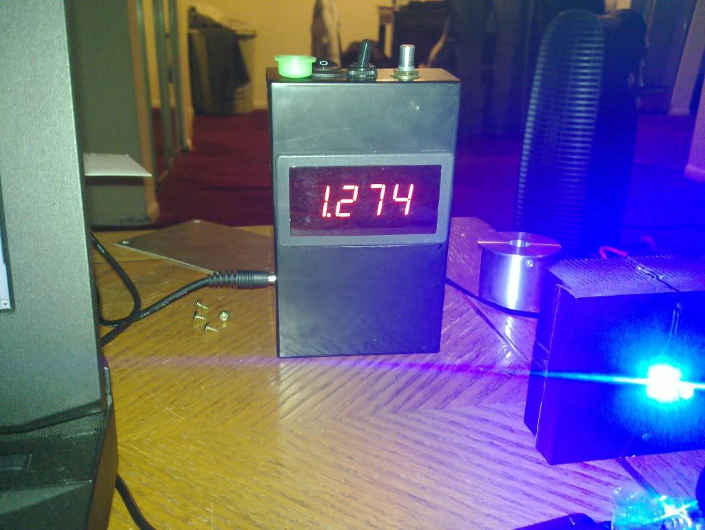
m140 445nm diode running at 1.267A, 405-G-2 (Rochester precision optics A671 or A610 lens)

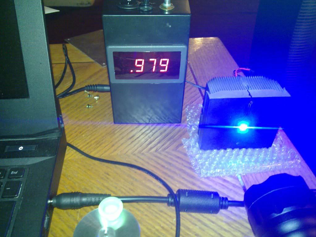
S06J 405nm diode running at 745mA 405-G-1 (Rochester precision optics A671 or A610 lens)

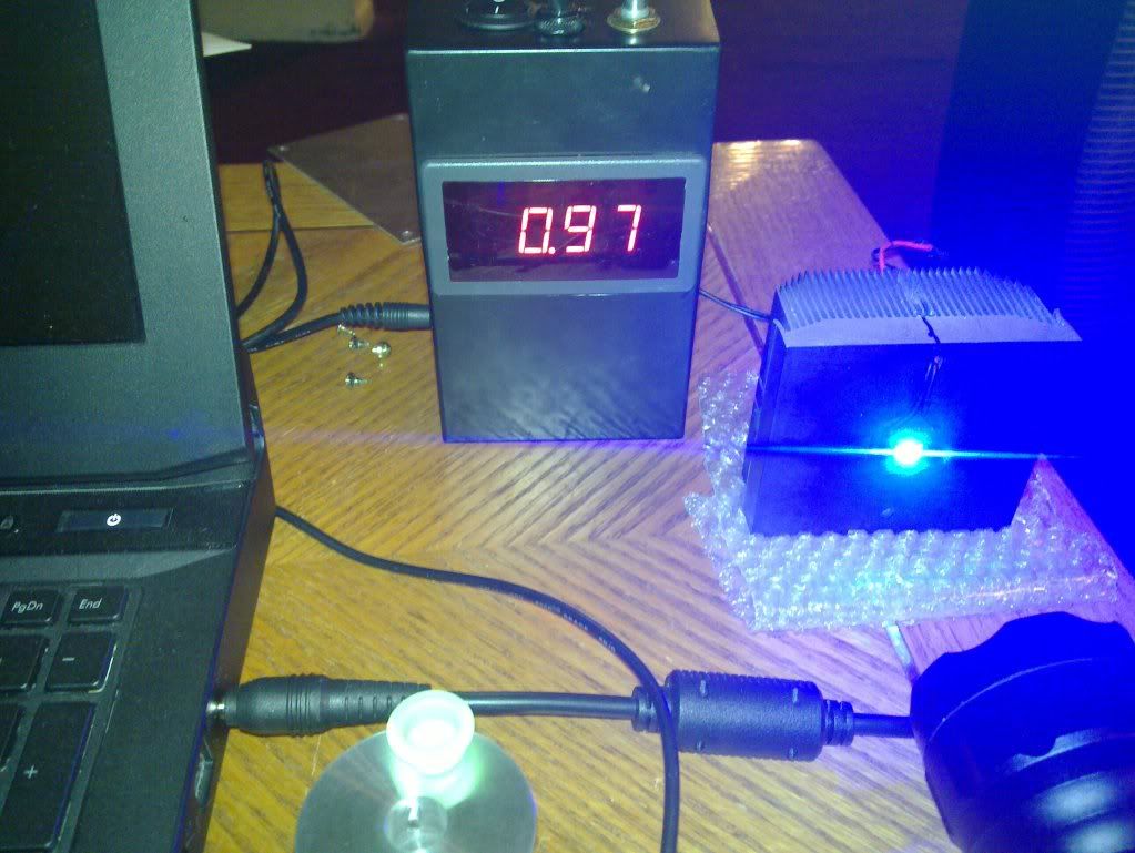
And here I flipped the ranging switch to high on the same laser:

I actually ran it in High first and than flipped to Low so the reading went up a bit in the meantime. In any case the ranging circuitry works fine.
I got the calibrated LPM back on Saturday, and remeasured all my lasers. Justin also sent me a PM saying that the configuration of the TEC, Heatsink and coating layers resulted in a sensor that was able to measure his most powerfull ~3W 445nm laser (this one perhaps: http://laserpointerforums.com/f39/fs-2-8w-3w-peak-445nm-maglite-295-a-77438.html) after calibration. In addition he confirmed the measurements of his 635nm lasers.
I have initially wanted to use a smaller heatsink, but decided to use an existing CPU aluminum heatsink. The surface to which the TEC was glued (using Arctic Silver Epoxy) was sanded with the finest grade sandpaper I could find in Lowes. Cleaned with alcohol and the TEC was glued. I have used the press with rubber pads to push the TEC as close to the metal as I could and let it dry for several hours.
After that the heatsink and TEC were sprayed with multiple layers of above mentioned Rust-oleum spray letting individual coats dry off for a minute or so.
Then I connected the sensor to the wires from LPM and determined which wire is positive and which is negative (shined the laser, if the neg values grow, switch the wires around). Soldered everything back together and done.
Below are some of the pictures:
Red LPC-815 650nm Diode running at 450mA, aixiz glass red lens

m140 445nm diode running at 1.267A, 405-G-2 (Rochester precision optics A671 or A610 lens)

S06J 405nm diode running at 745mA 405-G-1 (Rochester precision optics A671 or A610 lens)

And here I flipped the ranging switch to high on the same laser:

I actually ran it in High first and than flipped to Low so the reading went up a bit in the meantime. In any case the ranging circuitry works fine.
Last edited:


