Welcome to Laser Pointer Forums - discuss green laser pointers, blue laser pointers, and all types of lasers

LPF Donation via Stripe | LPF Donation - Other Methods

Links below open in new window

ArcticMyst Security by Avery

DIY Laser Power Meter Projects...

Trevor

0
Joined
Jul 17, 2009
Messages
4,386
Points
113
Troll fail....:cryyy:

Call it what you want, I'm just calling it like I see it. ;)

No... I'm referring to all findings on the Forum including our own
in shop tests of these OPHIR 20C Heads...

I'm definitely not discrediting a well known companies products..
What I am saying is that we have seen on the Forum and in our
shop, OPHIR surplus sensors off eBay that were up to ~10% off
calibration.
I'm just saying... don't believe that the OPHIR sensor that you
may get is 100% accurate without verifying it.

You are very aware of this since you even tested that head for
that other member that found discrepancies between his LaserBee
2.5W USB and his OPHIR head...
It was later found that the problem was the OPHIR head reading
~9%-10% too high and was reported on the Forum..

That is one Ophir head that was confirmed to be off.

If you have collected a statistically significant amount of data, by all means post it, and have it be independently verified.

Anything you (as a single person) come forward with cannot be counted as credible - that would be unscientific.

Since you referred to the heads that you had reported on and recently
sold.... I know that you corrected your 1st post data to show that your
initial readings were OFF due to your brand new Coherent Cube Laser
being off by ~9%....:thinking:

It was system donated to me with about 100 hours on it; basically new, but I suppose they had to be willing to donate it for some reason.

I hope that data sums it up for you....:)

These are only a couple data points, and do not prove anything. You know better, Jerry.

There is no proven systematic inaccuracy of Ophir heads. You are making the claim, it is up to you to prove it. What we do here is science, not smoke and mirrors.

Trevor


Joined
Oct 28, 2007
Messages
2,631
Points
48
Don't forget about knimrod's computer interfacing addon for his LPM... that was a big part of the project!

Great thread btw,

Regards,

amk
 
Joined
Sep 20, 2008
Messages
17,622
Points
113
Don't forget about knimrod's computer interfacing addon for his LPM... that was a big part of the project!

Great thread btw,

Regards,

amk

I just added that 2nd part of Nimrods Interface for his
DIY LPM project to the 1st post...
Thanks for reminding me...:beer:


Jerry

You can contact us at any time on our Website: J.BAUER Electronics
 
Last edited:
Joined
Feb 7, 2012
Messages
977
Points
0
So I got my Ophir sensor yesterday but it did not come with a molex conector cable. So I am unsure what is the corect pinout for it. It is a 150C-A-.1-C/ERB I have made a molex conector and leads but I dont want to hook this up backwards.

7039-img-4046.jpg


Here is a pic Could someone help me figure out the pinout on this? I have 2 different diagrams of how to wire this up and it's getting confusing.

Thanks in advance

Kent
 
Joined
Dec 27, 2011
Messages
2,062
Points
48
So I got my Ophir sensor yesterday but it did not come with a molex conector cable. So I am unsure what is the corect pinout for it. It is a 150C-A-.1-C/ERB I have made a molex conector and leads but I dont want to hook this up backwards.

7039-img-4046.jpg


Here is a pic Could someone help me figure out the pinout on this? I have 2 different diagrams of how to wire this up and it's getting confusing.

Thanks in advance

Kent

Hey Kent,

I went with this wiring diagram.


Ophir LPM Schematic by tsteele93, on Flickr

I'm sure you know this, but I will add that dots or circles mean that two wires CONNECT and a round JUMP or Semi-Circle means they do NOT connect, that is just where they had to cross in the drawing but they do not connect electrically.

If you look here, you can see my head with the wiring and actually I think both of the wiring diagrams you are seeing should end up being the same.


Untitled by tsteele93, on Flickr

If you are looking at this one...

http://laserpointerforums.com/attac...diy-laser-power-meter-projects-ophirtodmm.pdf

It is correct by COLOR but not in the correct order. Mine is in the correct positions. Does that make sense? I'll add your colors as well...

So the far left pin is orange/+out; BLUE BLUE
The next pin is red/+in ; GREEN GREEN
The next pin is brown/-out AND middle rail voltage (ground) YELLOW YELLOW
The far right pin is black/ -in from low power side BLACK BLACK
 
Last edited:
Joined
Feb 7, 2012
Messages
977
Points
0
I have seen that but it conflicts with this one.
So that's what has me confused..

7041-ophirtodmm.jpg


This one suggests it is dmm, ground, V-, V+
your diagram suggests dmm, v+, ground, v-
 
Last edited:
Joined
Dec 27, 2011
Messages
2,062
Points
48
I have seen that but it conflicts with this one.
So that's what has me confused..

7041-ophirtodmm.jpg


This one suggests it is dmm, ground, V-, V+
your diagram suggests dmm, v+, ground, v-

That one has the colors correct, but the wires are in no particular order. So it is correct, but only by color. Not position.
 
Joined
Dec 27, 2011
Messages
2,062
Points
48
:beer:

I had the same problem when I was doing mine, but it was easier for me to figure out because I had the correct molex pin so my colors matched that diagram even though the positions did not - so I was able to put it together that the picture was just showing the wire colors in no particular order.
 

benmwv

0
Joined
Sep 10, 2010
Messages
1,380
Points
48
Are the Ophir 150C suitable for visible lasers? They are made for high IR lasers right?
 
Joined
Dec 27, 2011
Messages
2,062
Points
48
I wondered about that as well but everyone and everything I read said they would work for any visible light lasers as well.

I tested mine up against my LaserBee with blue and red and came up almost EXACTLY the same!

Ophir head DIY LPM test - red and blue
 
Last edited:
Joined
Feb 7, 2012
Messages
977
Points
0
Well I went out to wallmart to grab some converters but they didnt have any so I went with the 9V battery option. I just tested my phr-805T I built the other day and I got 42ma on the Laserbee 2.5WUSB and 41ma on the Ophir and a 9mm 445 was a 746ma on the laserbee and 744 on the ophir. then a mits110 638nm and I got 70ma on the laserbee and 74ma on the ophir. So it is out a bit seems to be more so on the red. These were just quick tests. Since the ophir has such a quick response time I just fired up the laserbee till it peaked then quickly moved the laser onto the ophir Not the greatest procedure but it gives me an idea of how close they are.

On another note I was expecting to have to change out my 20$ ebay multimeter (A830L from onlybatteries.com) but it seemed to read this no problem. So you may be fine without the expensive fluke etc...
 
Last edited:
Joined
Dec 27, 2011
Messages
2,062
Points
48
That is great! Those are excellent results! Good job Kent. :beer:

That was my method too BTW.
 
Last edited:
Joined
Feb 7, 2012
Messages
977
Points
0
Yep it turned out great.. Now to get it hooked up to a arduino for data logging and a display. And stick it in a nice box... Had to play arround with it a bit so I decided to throw the 2.5W and a 1.7W at it. the batteries in the 1.7 havent been charged in a while but still got just over 4W on the sensor..

7044-img-4058.jpg


7045-img-4067.jpg


Hopefully that board RHD was working on comes out of the woodwork... :) Busy Busy!

Also thanks Tom for pointing me in the rite direction for that sensor. I love that I dont have to multiply by 3... :thanks:
 
Joined
Dec 27, 2011
Messages
2,062
Points
48
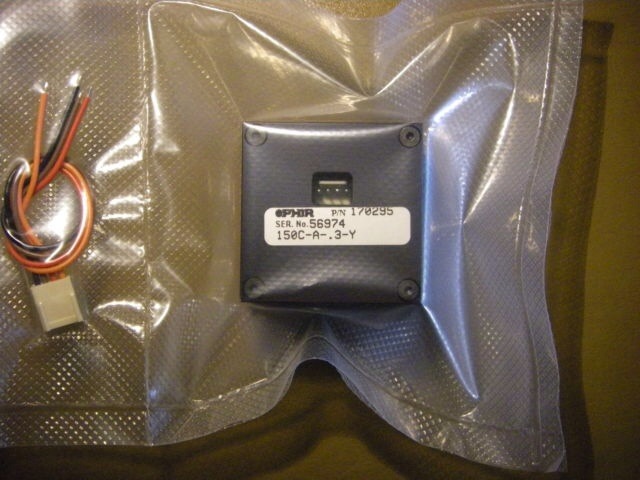
Yeah, I bought the .3 version because it was still new in packaging and I liked the idea of being comfortable with it not having been abused beforehand. But I doubt it matters much. It looks like yours is working just fine!


Top