Welcome to Laser Pointer Forums - discuss green laser pointers, blue laser pointers, and all types of lasers

Buy Site Supporter Role (remove some ads) | LPF Donations

Links below open in new window

FrozenGate by Avery

DIY laser driver question

nztdm

0
Joined
Jun 18, 2012
Messages
67
Points
0
I am powering an M140 diode from 2x18650 in series. I am using an LM317 regulator with constant current circuit.

The problem is, I only get about 1.06A (multimeter in series with laser diode). I am aiming to get about 1.5A.

The LM317T is attached to a huge TO-3 heatsink and barely gets warm.

Im sure it would be a bit over the top to have to find more 1ohm resistors to put in parallel, or is that is what is needed to get 1.5A

Here is my circuit:

2hwgyyx.png


Hmmm, interesting.

Where did you buy your LM317T from? Not all LM317Ts can go up to 1.5A. In addition, those that can go up that high may only be for a certain voltage/power range. Only LM317Ts with a current output rating of "1.5A min" are guaranteed to be able to output that current at all voltage ranges.

Generally, its never a good idea to push component limits. I'd consider paralleling drivers.
 
Something isn't adding up which is why I suspected the driver. I googled LM317 current equation and heres what I got.
Lim.png


Vref is normally around 1.2-1.3V (again, need datasheet).

So, Iout = 1.2 / 0.33 = 3.64 A. Something isn't adding up. Your resistance value could be wrong, your driver may not be capable of handling what you are trying to do, or it may be a load issue.

Personally, I don't really use LM317 drivers for constant current because of issues like this. When I build a discrete current controlled circuit via my own design, I can have confidence in my output.
 
Last edited:
I measured amperages for different loads.
M140: 1.06A
1ohm: 2.2A
Short circuit: 2.3A

Unfortunately, i dont know what to make of this. What other circuit could you recommend that I could build for 1.5A for M140? What would be your own design?
 
So it doesn't appear that the LM317 peak current ability is the issue then. Sounds more like a peak voltage issue.

Diodes are unique cause its hard to use ohms law on them. V=IR , there isn't really a known R for diodes. Consequently, one normally uses a PIV graph or specification. Meaning at some current I, you should have a voltage drop of V. So, if you cannot provide the voltage required for a given I, you are then limited to what current is associated with your peak V. Any chance you know what the expected peak voltage drop across a M140 diode is at 1.5A? (sorry, i've been gone from lasers for awhile so thats a new diode for me)

A A140 diode needed 4.45V in order to be driven at 1.5A according to this thread.
http://laserpointerforums.com/f65/post-your-ma-mw-51432-10.html#post728480 btw, this is all assuming you have good heat sinking of the diode.

with 2x18650, i'd assume you would have enough voltage but perhaps not? Its important to take into account possible voltage dropout. So, at 1.5A, many LM317s have a dropout of around 2.5V. Then you got your series resistor of 0.33 ohms * 1.5A = 0.495 V. In addition to all this, i'm guessing you got cheap multimeter which probably has a crummy internal sense resistor which provides an additional source of dropout. Perhaps 1V from the meter?
This means your basically wasting 4V of your batteries power. So, 3.6V + 3.6V - 4V = 3.2V which is probably less than the voltage required for a 1.5A drive level.

To confirm this, try using 3x18650 and i'm guessing you will get the 2.2-2.3A you saw when close to short circuit. Which... btw is too much for a M140 i'm guessing. Use a resistance such that your short circuit current is ~1.5A.

What you need is a low dropout driver as well as a low voltage drop method of measuring current. In addition, you need to make sure your 2x18650 are fully charged such that their voltage is at max.
I'd perform the same test again with the exact same setup (with the m140, 2 x18650 + multimeter in series) and use a second multimeter to measure the supply voltage of your 18650s under load as well as the voltage as the voltage drop across the diode vs. what you should expect at 1.5A. That should give you an idea of where you are at.
 
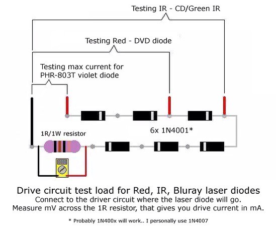
You might want to build a simple test load with five or six diodes in series and a 1 ohm resistor. Then you can measure voltage across the resistor and measure the current.

Like so...

http://laserpointerforums.com/f39/fs-selectable-test-load-up-3a-assembled-diy-kit-stock-63450.html


Test Load

I just grabbed this from google images, I'd use a more robust resistor and 3A or 6A diodes, and you may find different diodes drop different voltages, so check your data sheet.

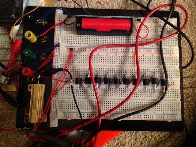
Oh yeah, I have a picture of one I threw together on a breadboard here...


Test Load tsteele93 by tsteele93, on Flickr
 
Last edited:
I think your resistance value is too low, and is just driving the LM317 into the ground.

The equation for LM317's in current config is:

Resistance = 1.25 / Target in A.

So R = 1.25/1.5

R = 0.8333333333 ohms

0.33Ohms is around 4A!

I would also maybe think about replacing the LM317, as you may have cooked it. Not worth risking an expensive diode for a cheap vreg.
 
Last edited:
You could consider using an LM350 (3A) or an LM338 (5A) instead of running the LM317 at it's absolute max. The resistor is calculated the same way as with the LM317.
 
Last edited:


Back
Top