

Benm
0
- Joined
- Aug 16, 2007
- Messages
- 7,896
- Points
- 113
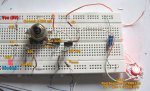
I've been doing some design work on a good current source for laser diodes, for example those from Senkat's group buys. The result of quite some experiments is the shematic attached to this post.
The design in a textbook current source, configured to meet the specific needs of a low-drop, high stability current source. Features:
- Current controllable trough a (low power, plain simple 10k) potentiometer, 0-300 mA range*
- Minimal voltage drop of only 0.9 volts at 200 mA, 1.0 volts at 300 mA.
- Commonly available electronic parts
Some measurements taken driving the red segment of an RGB powerled, Vf=1.99v at 200 mA:
Supply voltage -> output current
2.7 -> 044
2.8 -> 125
2.9 -> 200 (stable from a voltage drop of 2.9 - 1.99 = 0.9 volts)
3.5 -> 202
4.3 -> 199
5.0 -> 200 (calibration point)
10.0 -> 199 **
15.0 -> 202 **
* Range can be controlled by changing Rsense. For example, Rsense of 10 ohms gives a 0-30 mA current source, 0.5 ohms a 0-600 mA version.
** Maximum power of the transistor is 1.25W without a heatsink. For continuous operation at 200 mA, a heatsink is recommended if the input voltage is over 6 volts.


")