Welcome to Laser Pointer Forums - discuss green laser pointers, blue laser pointers, and all types of lasers

Buy Site Supporter Role (remove some ads) | LPF Donations

Links below open in new window

FrozenGate by Avery

[DIY] Driver for 635nm diodes, 200mA~ Cheap! And my PCB making tutorial, Easy!

^sry ur quite right about the chip ur using however most post on here about Vd are related to LM317, and im not sure anyone's questioning the low consumption of the lm1117 at about a volt.

Me :P said:
it looks to me the more you draw ..
draw as in current and yes its also temperature dependant.


Oh sorry, I misreaded that, I thaught you mean the more voltage you drop... stupid me, haha.
 
That leans back to needing to add the 1.25 ref voltage in the total.
I just got some LM1117LZ's in for low power builds. I was hoping to use 1 cell too.
Better start looking at the fully adjustable PSU.
 
Last edited:
Better start looking at the fully adjustable PSU.

this psu design was taken from TS317 (lm317) data sheet (im using this ic), probably what im gonna build and hook to my old P.C. converted psu (+/- 12v and +/- 5v)

labpsu.jpg


i also remember seeing a psu design on sams laser site
 
I recommend to you using a transformer, a diode rectifier and some capacitors to get at least 35 Volts for that power supply.

And using a pass transsitor too, to get some extra current.

In that case you wont only be able to use it for laser, but for all that needs power.
 
Last edited:
^indeed, tho im sure if i try with lower voltages it would work well as a laser driver, this will need some testing but im optimistic it will do the job.

i also found that psu design on sams laser site, its much the same but 12v and the volt adj and current lim are swapped, wonder why the ts317 lab supply is that way round as the volt adj ic must draw current from the 1st one to operate, maybe these chips really are that good at regulating the current..

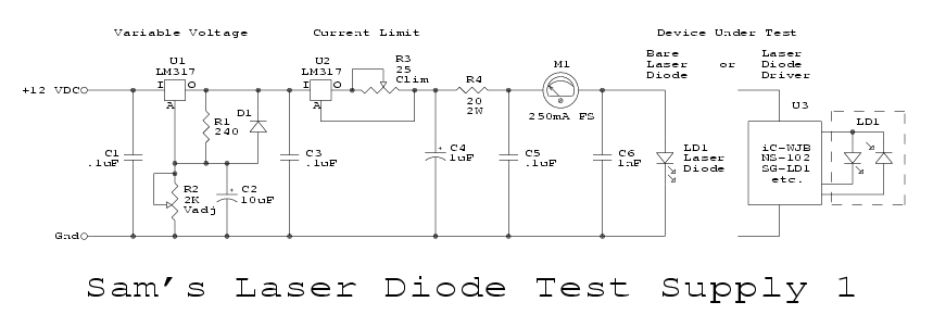
anyway that supply from sams site

sgldtst1.gif


whats your thoughts on that? tho i have to say his site has alot of laser driver designs, most of which use the photo diode to control output. lots of choices so little understanding on my part tho :(
 
LM317's can do two things. Either regulate current. Or regulate voltage. They can't do both at once however which is why Sam's circuit you posted has two. Generally with laser diode drivers though you don't have to worry about limiting voltage, since the output voltage will float to whatever it needs to be to maintain the set current.

This schematic you've posted is really more of a CC-CV power supply, rather than specifically a diode driver.
 
hmm so from what im understanding is this:
in current regulation the adj pin is acting as a floating ground with the load acting as the grounding path (acting like a current mirror?) and when in voltage regulation the 1.25 vref is compared to the adjust pin which is tied to ground though a dividing resistor, driving the gain of the output and fixing the voltage to a % of the Vin. :confused:
 
rafa, sorry the circuit didn't work. It is a good etching tutorial.
I spec'd the LM1117 after reading this thread and it indeed does require 1v less than the LM317.
I ordered a few of both style cases. The LZ will do up to 200ma builds and the T220 case will still do 1.5A.
In the example post #20 would be reduced to 7.4v.
I ordered the PSU posted by a member in another thread that has a digital readout and give complete control 0-2A and 0-15V. This way I can build the driver and find the minimum voltage and current required to operate. Then I can decide on a host and battery choice I'm pleased with.
YH-1502DD+ ADJUSTABLE VARIABLE DC POWER SUPPLY- 15V 2A - eBay (item 220675992230 end time Oct-28-10 18:38:16 PDT)
 
I bought LD1117 from mouser. I also have LM78L05 (TO-92) and LM317 (TO-220) chips, so I did a comparison for my personal education. I used a bench-top PSU to find the minimum Vin to put out 150mA into 4x diode test-load for each of the chips, Vout in all cases was around 3.1V:

LM317 5.2V
LM78L05 4.8V
LN1117 4.2V

The circuit was DDL, no current limiting resistor, 100ohm pot turned all the way down to ~1 Ohm.
 
Last edited:
comradmax, Interesting data. Earlier we got off a little on weather the 1.25 Vref was needed to be added in. Its easy to make a case either way in theory. rafa's design, if worked, would have shown the 1.25 Vref did not need to be added in to the total Vin if the LM1117 was used allowing 1 Li-Ion @ 3.7(max 4.15-4.2V). So, he says now the design didn't work. Ok, np there. Things don't always come out as expected.
Your results show that as a min threshold for operation if I'm reading it correctly. Yet, 5V allowed rafa's design to work. Extremely close. It may be that rafa's battery didn't reach the 4.2V and would have worked for a short time if it had.
Good info coming out here.
My tnx to all for their input. For me, this has been very informative.
 
I also tried 5V and 3.7V yesterday:) Below shown are mA/V for the test-load:

5V:
LM317------130/3.0
LM78L05---200/3.25
LD1117-----500/3.25

3.7V:
LM317------0/0
LM78L05---30/2.7
LD1117-----60/2.765
 
Thats odd to me and probably what rafa saw in his math.
Your 3.7V 1117 is showing 60ma @2,765V. According to the 635nm diode spec sheet, it should be lasing @ near 7mw. Is there a significant diff in a LD1117 vs an LM1117?
Need to look at the spec sheet on that. Good data.
Soon I should be able to assist on some valid input. There is a comment in another thread abt ohms law and reality. This looks like a perfect example where impurities in materials deviate from the pure projected outcome.
 
hmm so from what im understanding is this:
in current regulation the adj pin is acting as a floating ground with the load acting as the grounding path (acting like a current mirror?) and when in voltage regulation the 1.25 vref is compared to the adjust pin which is tied to ground though a dividing resistor, driving the gain of the output and fixing the voltage to a % of the Vin. :confused:

I think I see where your confusion is coming from. In both applications, the regulator is trying to maintain a 1.25V reference voltage (Vref) between Vout and A. When it's set up in current limiting mode, the resistor values between Vout and A determine what current draw Vref is attained at. The lower Vref is pulled, the lower Vout is. So as you can see, as current draw increases, the load pulls Vref down. The regulator in response cuts Vout until the current draw decreases once more to the point that A is seeing Vref.

When wired as a voltage regulator, it works basically the same way, only that instead of the current draw of the load controlling what voltage A sees, A is connected to a voltage divider that is sunk to ground. As the resistance of R2 decreases, Up goes the current, which drops the voltage A sees, which in turn, decreases Vout until the current decreases once more and equilibrium is achieved once more when A sees the proper Vref again. Sinking A straight to ground effectively clamps Vout at minimum output (Vref)
 
Last edited:
I didn't realize it was this easy to do homemade etching.

I have access to a LPKF Protomat at work, so I've just used that for a couple projects.


Back
Top