Welcome to Laser Pointer Forums - discuss green laser pointers, blue laser pointers, and all types of lasers

LPF Donation via Stripe | LPF Donation - Other Methods

Links below open in new window

ArcticMyst Security by Avery

DIY 445nm laser engraver

Joined
Feb 6, 2016
Messages
4
Points
0
Hello everybody,
I've read a ton of threads on this forum while designing the laser engraver that I'm currently building. I decided to ask all your guys expertise on my 2W 445nm laser. I've made the typical laser driver with an LM317 and a 22uf capacitor. I have a raspberry pi 2 to use to switch the laser on and off. For some reason it finally clicked in my head that I wouldn't be able to switch the laser on and off fast like a laser engraver requires, due to a capacitor being in parallel with the laser. I always thought that the capacitor acted as a filter and more importantly made sure the power didn't look like a square wave, which I heard was way easier on the diode. I'm confused on how engravers are able to turn the diode on and off so fast to engrave pictures, and still maintain diode life.
Any help is greatly appreciated.
Thanks,
Riot


Joined
Feb 26, 2015
Messages
1,359
Points
0
where did you get the diode from? most laser engraver buy the diode combo from DTR which includes diode/lens/module/driver.....

the LM317 maximum current is 1.5Amps so your laser output is no where close to 2watts.
and most newbie who build LM317 as a currrent regulator ended up as a voltage reg....
what was your input voltage and current?(what was your power source)....and as for the laser quickly turn on and off i'm not sure about that but i think you need a pulse circuit...
 
Joined
Feb 6, 2016
Messages
4
Points
0
where did you get the diode from? most laser engraver buy the diode combo from DTR which includes diode/lens/module/driver.....

the LM317 maximum current is 1.5Amps so your laser output is no where close to 2watts.
and most newbie who build LM317 as a currrent regulator ended up as a voltage reg....
what was your input voltage and current?(what was your power source)....and as for the laser quickly turn on and off i'm not sure about that but i think you need a pulse circuit...

Thank you for the response. I bought a 2W 445nm laser (2 watts being its maximum optical output is my understanding) with a module and everything at this link.
http://www.amazon.com/445nm-Diode-Copper-Module-Element/dp/B00HFHJBDI
I used a spare computer power supply to power the driver/laser. I made a voltage divider to get 7.2 volts as my input (that seemed to be the popular voltage that was used by most other people with a M140 diode). The design I followed for my laser driver is:
https://sites.google.com/site/dtrlpf/home/flexdrives/rog8811

Thank you.
 
Joined
Feb 26, 2015
Messages
1,359
Points
0
i think you need some sort of pulse circuit or something that can be modulate by computer... i'm not sure about that part but i see most laser engraver are control by computer....
 
Joined
Feb 6, 2016
Messages
4
Points
0
i think you need some sort of pulse circuit or something that can be modulate by computer... i'm not sure about that part but i see most laser engraver are control by computer....

Thank you for the response, I am currently using a Raspberry Pi 2 microntroller, I can use the GPIO pins to PWM a transistor? The problem is I still don't understand how a laser diode can be turned on and off that fast without shortening the diode life tremendously.
 
Joined
Feb 26, 2015
Messages
1,359
Points
0
diodes are design to be turn on and off quickly.... because if you look at their data sheet there is the pulse operation rating!!!
 

diachi

0
Joined
Feb 22, 2008
Messages
9,700
Points
113
Thank you for the response, I am currently using a Raspberry Pi 2 microntroller, I can use the GPIO pins to PWM a transistor? The problem is I still don't understand how a laser diode can be turned on and off that fast without shortening the diode life tremendously.

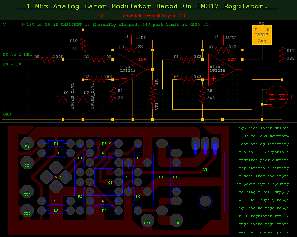
You could buy a driver with TTL/Analogue modulation built in - or if you're familiar enough with electronics you could build something like this:

ldschpcb.gif


You can even use an LM338 instead of an LM317 to get up to 5A output, instead of 1.5A.

The reason a lot of the drivers people use here have soft start is because a lot of the folk here drive their diodes rather hard, certainly above spec. The thinking is that a soft start will help the diode live longer when you are driving it hard. I'm not sure if that has ever been conclusively proven to be the case.

If anything, modulating a diode should increase it's life at a given current compared to not modulating it, due to a lower duty cycle. Assuming the output of the driver is nice and clean at least.

As was mentioned earlier, laser diodes in many applications are modulated very quickly, certainly into the megahertz range. They are perfectly capable of handling it, although in commercial devices they'll be running at or below spec.
 
Joined
Feb 6, 2016
Messages
4
Points
0
You could buy a driver with TTL/Analogue modulation built in - or if you're familiar enough with electronics you could build something like this:

ldschpcb.gif


You can even use an LM338 instead of an LM317 to get up to 5A output, instead of 1.5A.

The reason a lot of the drivers people use here have soft start is because a lot of the folk here drive their diodes rather hard, certainly above spec. The thinking is that a soft start will help the diode live longer when you are driving it hard. I'm not sure if that has ever been conclusively proven to be the case.

If anything, modulating a diode should increase it's life at a given current compared to not modulating it, due to a lower duty cycle. Assuming the output of the driver is nice and clean at least.

As was mentioned earlier, laser diodes in many applications are modulated very quickly, certainly into the megahertz range. They are perfectly capable of handling it, although in commercial devices they'll be running at or below spec.


Thank you so much for the clarification, these are the things I've needed to hear!!! Knowing that laser diodes can be switched on and off at rated currents without damaging them is great to know. Instead off overdriving and modulating the diode, I think I am going to just use a single GPIO pin to turn it on and off based on the Gcode commands. I'm trying to decide between an electromagnetic relay, solid state relay, or a transistor of some kind. The only bias I have up to this moment is the fact that electromagnetic relays are relatively slow. I'm not sure if it'll be fast enough for raster engraving or not. If anybody has any opinions they would be greatly appreciated.

Thanks for the responses,
Riot


Top