Well, Here's my contribution to the cause. I don't know if anyone has done this yet, but I searched around, and did not see any trace masks made up. The only pcb related stuff I could find was the group buy.
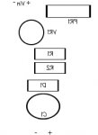
So I went ahead and created a black and white trace mask for the ddl circuit, for people who would like to try their own etching. I've rearranged the layout a tad from the group buy layout, to make it more amenable to home etching. However this brought the size down a tad width wise as well. I did not do a component mask, but I can if there are enough interested to justify it. The placement of the components is pretty self-explanatory.
Things I changed:
*Location of battery negative
*Location of the Pot
*Added vertical mounting option for the diode
*Added mounting holes at the corners
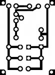
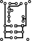
It's currently a size that is likely a bit large for the ideal board, I've done this to make it easy to solder for the novice who would like to try his hand at home etching. It should probably be bigger than the size they are going for in the group buy. The reason being, is that there will be no solder mask to prevent you from over soldering, and shorting things together. However, a poor man's way to solder mask is to get some tiny screws place them through the holes, and shellac the board, or, use clear finger nail polish.
If you are confident in your abilities, you can resize it and mod it to whatever dimensions you would like. I've also left a space on the left hand side for you to add a little text to your board if you like. Note: I'm told you will probably burn through a few of these etching boards, testing etc before you get it right if it's your first time doing this.
A few suggestions I've had was to resize it, and print it out, and place your components pins over the holes to see if they mount how you would like them to.
If you resize it, you might want to consider editing the picture a bit to change the LM317 pin holes to the correct width, the optimum range of which is just under 1/10 of an inch to just over.
The current version and size is based on the pin spacing for the lm317 (top right three holes).
So here you go.... Just etch and drill")
OH... Here's an etching tutorial for you folks. There are tons out there in addition to the instructions in the radioshack kit.
However, this one emphasizes safety really well. Make no mistake, this is NOT something you want to do carelessly, unless you don't care how many fingers you have. http://revision3.com/systm/etching/
Rich.
So I went ahead and created a black and white trace mask for the ddl circuit, for people who would like to try their own etching. I've rearranged the layout a tad from the group buy layout, to make it more amenable to home etching. However this brought the size down a tad width wise as well. I did not do a component mask, but I can if there are enough interested to justify it. The placement of the components is pretty self-explanatory.
Things I changed:
*Location of battery negative
*Location of the Pot
*Added vertical mounting option for the diode
*Added mounting holes at the corners
It's currently a size that is likely a bit large for the ideal board, I've done this to make it easy to solder for the novice who would like to try his hand at home etching. It should probably be bigger than the size they are going for in the group buy. The reason being, is that there will be no solder mask to prevent you from over soldering, and shorting things together. However, a poor man's way to solder mask is to get some tiny screws place them through the holes, and shellac the board, or, use clear finger nail polish.
If you are confident in your abilities, you can resize it and mod it to whatever dimensions you would like. I've also left a space on the left hand side for you to add a little text to your board if you like. Note: I'm told you will probably burn through a few of these etching boards, testing etc before you get it right if it's your first time doing this.
A few suggestions I've had was to resize it, and print it out, and place your components pins over the holes to see if they mount how you would like them to.
If you resize it, you might want to consider editing the picture a bit to change the LM317 pin holes to the correct width, the optimum range of which is just under 1/10 of an inch to just over.
The current version and size is based on the pin spacing for the lm317 (top right three holes).
So here you go.... Just etch and drill
OH... Here's an etching tutorial for you folks. There are tons out there in addition to the instructions in the radioshack kit.
However, this one emphasizes safety really well. Make no mistake, this is NOT something you want to do carelessly, unless you don't care how many fingers you have. http://revision3.com/systm/etching/
Rich.


") you can make approx. 3 gallons for 13$(4$ for 1 gallon of acid and .50$ for each container of peroxide) :
you can make approx. 3 gallons for 13$(4$ for 1 gallon of acid and .50$ for each container of peroxide) :