Welcome to Laser Pointer Forums - discuss green laser pointers, blue laser pointers, and all types of lasers

Buy Site Supporter Role (remove some ads) | LPF Donations

Links below open in new window

FrozenGate by Avery

Dark Sensing Circuit help

Joined
Dec 17, 2012
Messages
2,081
Points
63
I'm trying to make a simple dark sensing circuit and I cant get it to work. Everything is wired up like the diagram I found. Only time I can get the relay to actuate is when I turn the pot all the way down. The photocell is doing nothing. What did I do wrong?


Hmm, I'd probably use a comparator for something like this, much more reliable, however that circuit should work. By turning the potentiometer all the way down, I assume you mean so that the voltage going into the transistor base increases?
 
Counter clockwise. Not sure what that does. I was going off of pictures and part numbers. Still learning this stuff. Whats the circuit you speak off? What this will be for if I ever get it working is an RC multirotor. When it gets darker than the set limit it switches on nav lights automaticaly so it doesnt eat up an rc channel.
 
Get some measurements of current through the photocell branch, and some measurements of base voltage. Do this for varying stages of incident light.

As an alternative, you can take a small microcontroller like an AVRtiny to read the photocell and switch a GPIO in response. It would be very cheap, require fewer components, and be more lightweight.

You could also choose to switch a MOSFET instead of a relay - it would save you extra weight, and battery life (by limiting the current through your transistor to something low - just use the transistor as a pull up resistor). The transistor would just be switching a voltage instead of having to sink unnecessary current flow.

You could also put the drain of the FET at 5V to run it in triode mode allowing for variable current through the FET with varying lighting conditions.
 
Im still at the level where I need pictures of circuits in order to build them :( light weight with minimal battery draw would be the best thing. More power for my motors.
 
Couldnt measure current of the photocell part but I did measure current of the entire unit and it fluctuates with how much light is applied to the photocell. Only a few mA though. The voltage at the base would change 3 or mV. Though I could have been measuring that wrong. As I turned the pot it would increase or decreas where that 3mV change was.
 
Looks like your base current is too low. I strongly recommend using a comparator as mentioned above. Even if you get this to work by tweaking the values, the turn-on value will be soft, so your relay contacts will not close properly. A comparator solves this.
 
KnowledgeMaze.jpg


I think it's time you did some googling. We're quickly approaching the line between help and spoon-feeding.


Fixed. There's a way around it.

You're not a trollin' newbie, I know that.

Start with something like this basic circuit:
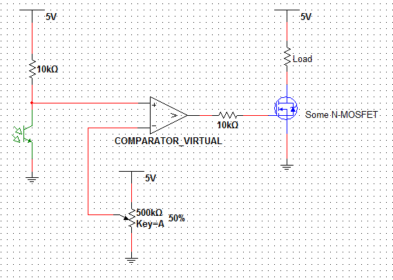


It uses a voltage divider, whose output is dependent on incident light - right?

Cool, now take an op - amp or a comparator and take that varying voltage, and compare against some reference voltage you adjusted by turning the pot.

When it gets too dark, the photoresistor/transistor (whatever you choose) will become more resistive, and a higher voltage will appear across it. As soon as that voltage goes higher than the compared reference voltage you set on the (-) input, the comparator will swing its output to the +Vcc state (+5V) in this case. That swing to a positive voltage puts the MOSFET into saturation mode and it becomes a very small resistance. This turns on your 'load' - whatever that it is.

The MOSFET must be able to handle the load current, the comparator must be able to run at your Vcc - whatever that is - and so on. Give this circuit a try, and experiment with it until it works how you'd like it to.

Both comparators and MOSFETs are 'voltage' controlled devices and will require very little current to operate. I think you'll find that something like this circuit draws very little power. Good luck with your build!

:)
 
Last edited:
Ahh thats perfect. That gives me enough info and a direction to go in. I gues its off to radio shack to get some components. Anf a breadboard. Dont feel like soldering up a bunch of things again only to not have done it right haha.
 
The only issue I see is mosfets saturate at 10V, so your Vcc for the comparator should be >10V (make sure you choose a comparator compatible with >10V or so) unless you get special logic level mosfets.

You should also know that by convention the supply Vcc and ground pins of opamps, comparators, and many other ICs are not shown on schematics by convention. Likewise a decoupling 0.1uf cap across supply and ground right at all ICs to prevent self oscillation and ringing should be used.
 
You should probably also add an RC circuit with a small time constant to the gate of the FET to avoide very abrupt switches/ lets the gate "ramp up" to HIGH state and prevent sudden (sub microsecond) voltage fluctuations.

But get the basic circuit working first. :)

This will work with any MOSFET with a Vth < Vcc
 
The only issue I see is mosfets saturate at 10V

That's not true at all. The gate voltage required for saturation depends on the drain current and the particular mosfet. It can be as low as a volt, or as high as a few tens of volts.
 
That's not true at all. The gate voltage required for saturation depends on the drain current and the particular mosfet. It can be as low as a volt, or as high as a few tens of volts.

Only because I technically used the wrong term. For a MOSFET "saturation" is when a rise in Drain voltage no longer results in a rise in Drain current. It occurs when the gate voltage is above the threshold voltage and the drain voltage is above the difference between the gate and threshold voltages.

However, I meant the term saturation in the BJT sense where it is used to describe when additional gate bias no longer results in additional current output... i.e. when the device is fully ON (or for an enhancement mode mosfet "fully enhanced"). This point occurs at between Vgs = 8V and 10V.

If you take a standard mosfet, say an IRFP260 (overkill for the application - I know) and apply a Vgs of 5V the mosfet will act like a high value resistor between D and S. The result is a huge voltage drop and very little current flow.


Back
Top