Welcome to Laser Pointer Forums - discuss green laser pointers, blue laser pointers, and all types of lasers

Buy Site Supporter Role (remove some ads) | LPF Donations

Links below open in new window

FrozenGate by Avery

Coherent Kenometer mod to get 10W reading??

Joined
Dec 17, 2010
Messages
1,144
Points
48
So, I bought my Kenometer with Coherent thermopile back in August (I was at SELEM at the time. ;) )
This was supposedly the last one the Kenom ever sold.

Anyway, when he sold it to me, he said that the digital readout will meter up to 2W.
He then said that I can read up to 10W by attaching a DMM to the test ports on the back of the meter.
This is where I am having issues.

This is a pic that I found of another member's Coherent Kenometer.
See the test ports on the back and the switch on the side (to change the output from digital readout to DMM ports)?
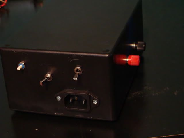
Kenometer10Wrearport.jpg


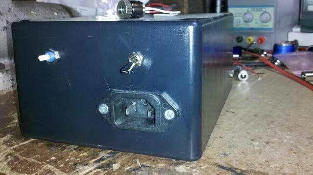
This is a pic of my Kenometer....
2011-12-12_00-42-45_280.jpg


Yup....methinks something is missing. :thinking:

My question is; does anyone know how to go about wiring in the ports and switch to use a DMM and meter up to 10w?
It is annoying that I can only meter to 2W when I know what that awesome sensor is capable of. :(

I have pm'ed Kenom, but everyone knows that is a lost cause as of late...:can:
It is supposed to have a year warranty, but he never responds.

Can anyone help me out? :anyone:
 
Last edited:


I'm not familiar with the insides of a kenometer, but maybe it's possible to just bring the leads from the panel meter to connectors on the outside. Reasonably easy to do, depends on the circuit if it would actually work.
 
^It'll work. You're just changing one voltmeter for another. Unless your volt meter has a low input impedance (and it doesn't) then there will be no problem.
 
I'm not familiar with the insides of a kenometer, but maybe it's possible to just bring the leads from the panel meter to connectors on the outside. Reasonably easy to do, depends on the circuit if it would actually work.

The link I posted above shows the inside of the Kenometer...

It seems clear to me that the bannana plugs on the OP's kenometer
no doubt connect to the 2nd toggle switch which chooses the internal
meter or the external LPM...


Jerry
 
Last edited:
A big :thanks: to all that have replied.

I never found that thread through the search function, Jerry.
The search of the forum sucks since the search window disappeared. :cryyy:

Taking the input leads off of the display and running them to a selector switch sounds easier.

But Jerry's mod looks to be the right way to do things. :)
The "you may end up with a nonfunctioning kenometer" kind of worries me, though. :undecided:

What would the DMM be set to if using it to read mw?

Thanks again for the input, guys. :D

The Search Bar is still there... It had been moved to the bottom
of every Forum Page because it took so long to load and it made
the pages jump when it finally did load. Look under the Reply Box.

Take pictures and make drawings of all the connections BEFORE
you do any mods so that you can bring it back to its original state.

Using a DMM the output is still 1mV/1mW.... So if you are measuring
4 watts set the DMM to 20V or as low as you can get a full 4000mV
reading.
At the 20 Volt scale you will only have a resolution of 10mV. That is
to say that the DMM display will only change with 10mV of input.

The DPM we chose for the project will read up to 20Volts in 1mV
increments without needing to change the reading scale and such
has a resolution of 1mV.


Jerry
 
If you are referring to the 10W LPM Project... we got those
on eBay at the time of that project as is show in the parts
list on that Thread...


Jerry
 
Last edited:
The Search Bar is still there... It had been moved to the bottom
of every Forum Page because it took so long to load and it made
the pages jump when it finally did load. Look under the Reply Box.

Take pictures and make drawings of all the connections BEFORE
you do any mods so that you can bring it back to its original state.

Using a DMM the output is still 1mV/1mW.... So if you are measuring
4 watts set the DMM to 20V or as low as you can get a full 4000mV
reading.
At the 20 Volt scale you will only have a resolution of 10mV. That is
to say that the DMM display will only change with 10mV of input.

The DPM we chose for the project will read up to 20Volts in 1mV
increments without needing to change the reading scale and such
has a resolution of 1mV.


Jerry

Thanks, Jerry.

I had thought that had read somewhere that the Coherent setup wasn't the standard 1mV=1mw like the Ophir.
That helps alot.

:thanks:
 
Thanks, Jerry.

I had thought that had read somewhere that the Coherent setup wasn't the standard 1mV=1mw like the Ophir.
That helps alot.

:thanks:

The Coherent Head alone does not output 1mV/1mW....
It is the Coherent PCB in the Kenometer that amplifies
the Head's signal to the 1mV/1mW level...


Jerry
 
The Coherent Head alone does not output 1mV/1mW....
It is the Coherent PCB in the Kenometer that amplifies
the Head's signal to the 1mV/1mW level...


Jerry

Great! That means that I could use your data logging module to graph my output in Eagle Eye.
Ill have to add that to the future modificatons list. :D

UPDATE: Kenom has offered to make things right and repair it. :)
 
Last edited:


Back
Top