Welcome to Laser Pointer Forums - discuss green laser pointers, blue laser pointers, and all types of lasers

Buy Site Supporter Role (remove some ads) | LPF Donations

Links below open in new window

FrozenGate by Avery

CO2 Power Supply Schematic Help

Because I was planning to make the transformers and did not want to wrap 20000 coils of wire :p

The real problem is the fast HV diodes.
They are difficult to find and expensive.
That is another reason why we are using TV
flyback transformers. They are already
wound for us and have all the diodes and
everything we need inside.
 
Last edited:


Is it something like this?

HeNe%20Driver.gif

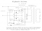
I'm not sure what kind of driver that is. When I was looking to buy a 40W Co2 driver off ebay they looked to be some kind of flyback transformer driver anyways so I decided to just use the driver I had already built and it works great.

Here is the link to the driver I'm referring to

Royer oscillator - HvWiki
 

Attachments

  • 478px-Mazzilli_flyback_driver.png
    478px-Mazzilli_flyback_driver.png
    106 KB · Views: 309
I'm not sure what kind of driver that is...Royer oscillator

It's basically just a single-ended version
of that using a darlington pair to spread
out the heat a bit. A Royer is fine for an
AC transformer, but with a DC flyback, most
of the driving will be only on the one end
anyway.
 
The off the shelf drivers I believe are half bridge SMPS using a SMPS IC and current feedback .

The larger ones use 2 fly back style transformers in series and the smaller ones just a single transformer .
 
Those diodes are excellent for an NST. Just
don't expect them to work at higher
frequencies. The capacitors will work at any
frequency within reason.
 
There are... WAY too many things wrong with that schematic. Here are a few things that jump out:

3k in series with mains? Why? That wastes power and limits your power draw from mains to 2W.

Bridge is wonky.

Looks like bridge is sending DC into a transformer. Transformers don't work at DC.

CO2 lasers don't have three connections.

You've drawn your transformers as step-down.

Why is there an autotransformer after the switch?

Why is there an NPN even near 30kV? Transistors can't operate at voltages that high.
1. Thanks I didn't realize that
2. Was told that already ;)
3. Didn't notice that thanks for catching it.
4. The third lead is for ignition it is not considered a lead.
5. I thought primary was connected to input?
6. Is there something wrong with putting it after the switch?
7. I threw that there at the last second before saying, "Hey I am a noob at electronics and this is the first real schematic I have ever drawn let me post it on the forum for some help."

Thanks so much cyp! I will rewrite a revised one today and hopefully get it up for review.

:thanks: all you guys!

EDIT: What does having a resistor in series with mains do that is bad? I am really curious as in my new design I will most likely have to do that to reduce the 33kv output so that I dont pop the tube and the wattage rating of the resistor for that end would be a bit too high.
 
Last edited:
Wat.

In your most recent schematic remove the series resistor on the primary; the primary winding's inductive reactance performs all the necessary current limitation. The only thing that resistor will do is waste energy in the form of heat, drop voltage, and cripple the transformer's output.
 
Wat.

In your most recent schematic remove the series resistor on the primary; the primary winding's inductive reactance performs all the necessary current limitation. The only thing that resistor will do is waste energy in the form of heat, drop voltage, and cripple the transformer's output.

Is it ok to run the tube on 24kv without damaging the gas/tube?
 
Wat.

In your most recent schematic remove the series resistor on the primary; the primary winding's inductive reactance performs all the necessary current limitation. The only thing that resistor will do is waste energy in the form of heat, drop voltage, and cripple the transformer's output.

Yeah, all that and you are putting 12kV
into 10kV diodes. The peak voltage will be
12 * 1.414 = 17kV. The doubled open
circuit voltage is twice that, which means
you will need 4x. It will also need way
more capacitance, probably at least 100nF.
The right amount will have to be determined
experimentally. You will know when there
isn't enough because the tube will flicker,
go out and restrike on every half-cycle.
Keep adding more capacitance until the
flicker stops. It should look something
like this.

CO2_Laser_PS.gif
 
Last edited:
First off thank you guys so much for putting up with my noobishness and it is really great to have some teachers even if on a forum. :)

Yeah, all that and you are putting 12kV
into 10kV diodes. The doubled open circuit
voltage is twice that, which means they
will need to be tripled up. It will also
need way more capacitance, probably at
least 100nF. The right amount will have to
be determined experimentally. You will
know when there isn't enough because the
tube will flicker, go out and restrike on
every half-cycle. Keep adding more
capacitance until the flicker stops. It
should look something like this.

CO2_Laser_PS.gif
Ok so basically stick the 10kv diodes in series to triple their rating?

For the capacitor, can't exactly find many good priced capacitors in the nf range rated for 30kv. Would making my own work and be efficient enough?


Back
Top