- Joined
- Sep 22, 2010
- Messages
- 1,360
- Points
- 48
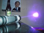
Ok before I solder this up permanently tomorrow and potentially fry my 6x diode I want to run this buy the knowledgeable folks here.
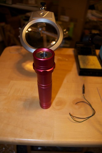
First here's the specs of the laser I'm building:
diode: 6x SF-AW210
driver: drlava microboost set to 180mA (get Flamingpyro's for this!)
power: 3xAAA NiMH until my 18650s $%^&(% arrive from DX.
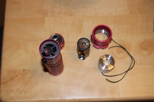
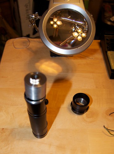
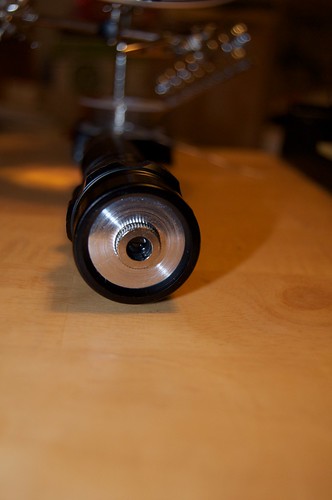
host: Mohernberg Guidesman 18650 Host+Heatsink these hosts are great and a *steal* at $20.
Here's what I've done so far:
Set the currant rage to 140-280mA per the manual on drlava's site.
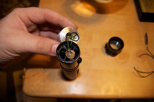
Soldered leads to the battery +/-.
Soldered leads to the D+/-.
For a test load I used 6 1N4001 diodes in series along with a 1ohm 1W resistor to measure the current across.
Since the host is case negative and the microboost doesn't have a continuous ground I also need to run a separate lead from the case pin to the negative of the input side correct? The +/- pins of the LD connect to the +/- leads from the LD side of the driver as normal. The positive lead from the input side connects to the positive terminal in the pill.
I also wanted to make sure I set up the driver and test load correctly since I've never tested a microboost before. I connected LD+ lead to the first diode and the LD- lead to the resistor then measured the current across the resistor. I wasn't sure if I needed do something different due to the lack of a continuous ground between batt- and LD-.
Thanks!
Last edited:


