D
Deleted member 49011
Guest
Hey ,
This was my weekend project that I have nearly finished ( just need to do low voltage PSU, Power connector )
The overall goal was a open top cassette player and stereo valve amp all in one box .
short video can be found here of it running - https://www.youtube.com/watch?v=yWrDe6XFIik&list=UUvjDVNxRU2DInDMQQw_iYJA
The cassette player is from a dead portable unit with the motor driver being replaced by a very low dropout PMOS voltage regulator
The preamp for the tape head is based in a Philips TDA1522 IC and the board its on is mounted to the front of the unit .
The Valve amplifier is based on the 12AU7 preamp tube and 50EH5 pentode with negative feedback .
Most of the cable are screened with one end grounded to avoid ground loops ( except for preamp , power stage ) , The preamp stage is fed via one shielded cable and the power stage is fed from a dual core screened cable from the output transformers .
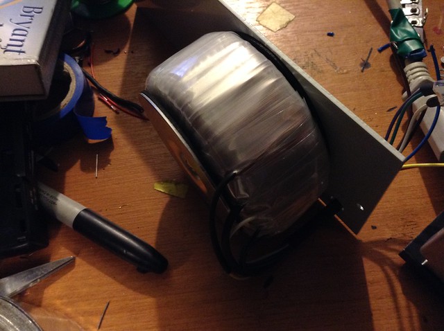
The power transformer was a custom one I had made to provide the 50V , 6.3V and 130V AC needed for the amp .
The tape preamp is run from 12V and the motor driver 3.7V ( power supply build in progress )
The unit dose have a AUX audio input with a DPDT switch for input selection ( Tape or external ) .
Worked out rather well : ) , No hum and good sound ( with proper speakers xD )
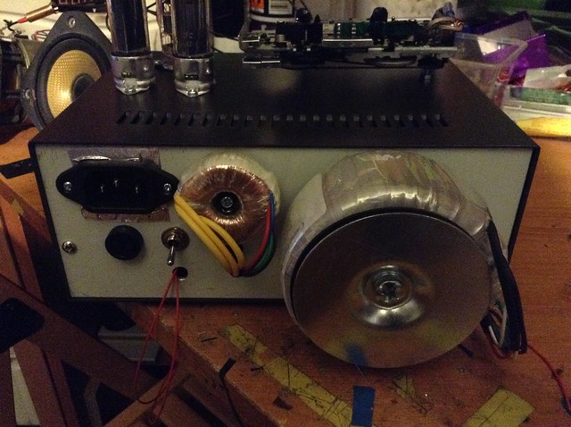
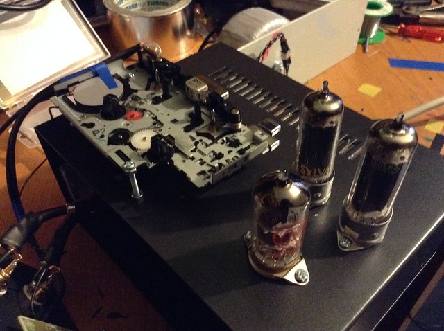
The inside , the black cable with the two red cables is the preamp side supply and the two red cables are the negative feedback to the preamp tubes cathodes ( other end is taken from speaker out jacks )
The other cable with the orange wire is the dual core from the output transformers and the orange cable is the supply to the output tube grid 2's
 IMG_0863 by TwirlyWhirly555, on Flickr
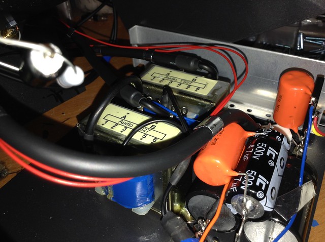
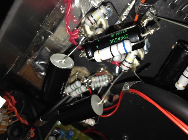
The 3 electrolytic capacitors and the two polypropylene capacitors and 2 resistors make up the power supply stage
 IMG_0867 by TwirlyWhirly555, on Flickr
 IMG_0868 by TwirlyWhirly555, on Flickr
 IMG_0869 by TwirlyWhirly555, on Flickr
 IMG_0871 by TwirlyWhirly555, on Flickr
This is the top showing the preamp tube ( front ) and the two power output tubes , The cassette player raised and held in place with two bolts and 6 nuts , its cables run though a cutout in the from panel .
The front panel , the board in the middle is the tape head preamp , left side is the speaker jacks and the right side in input selection switch , volume pot and 1/4" input jack .
 IMG_0874 by TwirlyWhirly555, on Flickr
This was my weekend project that I have nearly finished ( just need to do low voltage PSU, Power connector )
The overall goal was a open top cassette player and stereo valve amp all in one box .
short video can be found here of it running - https://www.youtube.com/watch?v=yWrDe6XFIik&list=UUvjDVNxRU2DInDMQQw_iYJA
The cassette player is from a dead portable unit with the motor driver being replaced by a very low dropout PMOS voltage regulator
The preamp for the tape head is based in a Philips TDA1522 IC and the board its on is mounted to the front of the unit .
The Valve amplifier is based on the 12AU7 preamp tube and 50EH5 pentode with negative feedback .
Most of the cable are screened with one end grounded to avoid ground loops ( except for preamp , power stage ) , The preamp stage is fed via one shielded cable and the power stage is fed from a dual core screened cable from the output transformers .
The power transformer was a custom one I had made to provide the 50V , 6.3V and 130V AC needed for the amp .
The tape preamp is run from 12V and the motor driver 3.7V ( power supply build in progress )
The unit dose have a AUX audio input with a DPDT switch for input selection ( Tape or external ) .
Worked out rather well : ) , No hum and good sound ( with proper speakers xD )
The inside , the black cable with the two red cables is the preamp side supply and the two red cables are the negative feedback to the preamp tubes cathodes ( other end is taken from speaker out jacks )
The other cable with the orange wire is the dual core from the output transformers and the orange cable is the supply to the output tube grid 2's
IMG_0863 by TwirlyWhirly555, on FlickrThe 3 electrolytic capacitors and the two polypropylene capacitors and 2 resistors make up the power supply stage
IMG_0867 by TwirlyWhirly555, on FlickrIMG_0868 by TwirlyWhirly555, on FlickrIMG_0869 by TwirlyWhirly555, on FlickrIMG_0871 by TwirlyWhirly555, on FlickrThis is the top showing the preamp tube ( front ) and the two power output tubes , The cassette player raised and held in place with two bolts and 6 nuts , its cables run though a cutout in the from panel .
The front panel , the board in the middle is the tape head preamp , left side is the speaker jacks and the right side in input selection switch , volume pot and 1/4" input jack .
IMG_0874 by TwirlyWhirly555, on Flickr
Last edited by a moderator: