Welcome to Laser Pointer Forums - discuss green laser pointers, blue laser pointers, and all types of lasers

LPF Donation via Stripe | LPF Donation - Other Methods

Links below open in new window

ArcticMyst Security by Avery

Blu-ray in a DX greenie CR2 housing

danq

0
Joined
Sep 18, 2007
Messages
835
Points
18
Nobody sent me any dead greenies from DX as I had asked, so this may become one-of-a-kind...

This was a pretty easy mod.

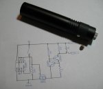
The DX red modules here fit almost perfectly into the DX green CR2-powered body once all the guts are removed.

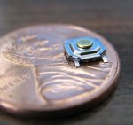
I don't like tail-switches, and wanted to use a push-button controlled multifunction circuit, so installed a tiny push switch on the front end. I kept the tailswitch as a safety, in case the push button gets pressed in my pocket.

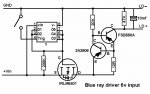
The circuit is pretty simple - just the generic 2-transistor regulator, being powered through a FET that's controlled by a special chip. That chip is out of a Photon Micro-Light; it provides dimming up/down, fast or slow blink, SOS, and momentary-on modes, all through the push-button. I've got this unit set for about 50mA current.

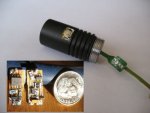
This circuit board is kind of ugly - I'm not too steady with the soldering iron (even when I can see the parts), and I actually changed the circuit a couple of times (breadboarding on a .7 x .3 board - yuck!)

The photos show the finished unit with the circuit diagram; front and back of the board with a dime for scale; and the head piece with the switch temporarily mounted. The flat cable on the right is from a dissected DVD burner - I used it because it's flat and tough and won't melt even at soldering temps. That gave me a set of connections in my head piece that were long enough to handle easily but folded very small for assembly. There's more value than a diode in those DVD units!

This runs on 2 rechargeable Lithium CR2's. To make that fit I had to chop the tail plug some, which was the hardest mechanical task apart from making the flat spot for the head switch (for which I used a hand-held Dremel)

[circuit edited/corrected 2/18/08]
 

Attachments

  • BlueWithPhoton_V1_smallfile_001.jpg
    BlueWithPhoton_V1_smallfile_001.jpg
    29.1 KB · Views: 184


danq

0
Joined
Sep 18, 2007
Messages
835
Points
18
Here's that second photo (a composite)

The parts on the topside of the board don't quite match the circuit in the first photo; it went through changes during construction. Now that I think of it, what's in the unit may be a little different from that diagram too... I had some problems with the special chip not liking the electrical environment...
 

Attachments

  • internals_smallfile.JPG
    internals_smallfile.JPG
    20.2 KB · Views: 164
Joined
Jul 24, 2007
Messages
2,749
Points
0
Funny thing is I was looking at my kaid greenie thinking that it looked a suitable host for a bluie....now I know it is. Very nice :).
I have never tried SMT devices but it looks like I need to give it a go. Could you post the circuit diagram and a parts list please? Or point me to a thread where it already exists?

Again, superb project all that is needed now is a beam shot :)

Regards rog8811
 

danq

0
Joined
Sep 18, 2007
Messages
835
Points
18
rog8811 said:
Could you post the circuit diagram and a parts list please? Or point me to a thread where it already exists?
umm.. perhaps this thread? ::)

The first pic has the circuit, all parts except the FET are labeled - that's an IRLM6401 P-channel rated at 3 Amps in an SOT-23 package.

The only part of that circuit in doubt is the voltage divider on the left side... I can't remember if that was the final thing that made the Photon chip happy.

Then there's that chip - comes out of a $20 micro-light. Nice bit of electronics, a bit pricey though! I think I could reproduce much of its function but not with one chip.

Oh, about the beam shot: I just figured everybody's already seen a blu-ray beam many times over...

:)
DanQ
 
Joined
Jul 24, 2007
Messages
2,749
Points
0
All read and understood

Regards rog8811

*Edit...I just wanted something I could print out, it may be of use to others once the chip is known ;)

* Another edit making the corrections suggested by Danq
 

Attachments

  • blue_driver01.jpg
    blue_driver01.jpg
    88.1 KB · Views: 224
Joined
Nov 25, 2007
Messages
270
Points
0
did you have to remove a massive amount of brass to fit the bluray's axis-like housing? could you get a picture from the front?
 

danq

0
Joined
Sep 18, 2007
Messages
835
Points
18
rog8811 said:
*Edit...I just wanted something I could print out, it may be of use to others once the chip is known
looks good... but remember I'm not sure about that voltage divider in front of the chip! and those pin labels are my own contrivance, not off some spec sheet ;)

lastly, I kinda doubt that specific chip will ever be known, at least in a useful generic economic sense, as I believe it is a proprietary custom chip, made only for the Photon micro-light people (someone please prove me wrong! they cost me $20 'cause I'm taking them out of the retail units). The chip says "Freedom" on it - that's the model of Photon it's from.
 

danq

0
Joined
Sep 18, 2007
Messages
835
Points
18
member02 said:
did you have to remove a massive amount of brass to fit the bluray's axis-like housing? could you get a picture from the front?
All the brass parts come out, except there's a retaining ring that I'm using to hold things in.

I'll try to get an inside shot soon.

DanQ
 

danq

0
Joined
Sep 18, 2007
Messages
835
Points
18
Rog, your diagram actually could use a mod or two....

- that 4K7 should be 47K
- the "E" at the FET should be a "G" (it's wrong on mine)
- the other 2 connections on the FET are Source, going to the V+; and Drain, going to the other trans' emitters.

and yeah, I'm going to have to open up my unit and inspect that circuit to resolve the question I have about that voltage divider. Maybe tomorrow.

:)
DanQ
 

danq

0
Joined
Sep 18, 2007
Messages
835
Points
18
OK, I've opened up my unit and checked the circuit - there is no voltage divider on the final version... so delete the 10K and 30K resistors, and put pin 8 of the chip to ground (-).

Not sure why that works, since I was having problems with the chip previously when it was getting the full 7 to 8 volts. Maybe changing to an FET on its output? it had been another FSB660A. Anyway, this should work.

DAnQ
 

danq

0
Joined
Sep 18, 2007
Messages
835
Points
18
As requested - detail photos:

upper left: Front end with focusing lense removed. The case's original beam-hole was enlarged to be just a bit smaller than the module. The threads visible through the opening are the inner wall of the laser module.

upper right: Back side of head assembly.

middle: Positive contact in rubber grommet; power and switch traces wrapped in Kapton tape; brass retaining ring.

bottom: Fully disassembled.

materials note: Kapton tape is Good Stuff! sticks well but comes apart; tough, resistant to puncture, and high heat tolerant (you can solder right next to it). It comes in various widths but I just got the 1/2" and split it with a sharp knife when I need it thinner. It can be very expensive but I've seen it on eBay for about $6-$9.
 

Attachments

  • innards_smallfile.jpg
    innards_smallfile.jpg
    153.4 KB · Views: 204

danq

0
Joined
Sep 18, 2007
Messages
835
Points
18
Their photo of it is really poor... so here's one with Mr. Lincoln
 

Attachments

  • micro_sw.jpg
    micro_sw.jpg
    50.4 KB · Views: 207


Top