Driving frequency ?
Anyway, yes, if it's just dimming, without show interruptions, then maybe it's the 10uF capacitor (usually 10uF, at least) that keep it "half-on" ..... maybe is enough to substitute the capacitors with 100nF or less .....
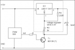
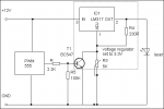
Also, check for the ceramic one in parallel to the LD (some units have one), that can be also 2 or 3 uF, instead a 100nF one ..... my o-like 170mW module have, as example, a 10uF (marked A106) at the input, and a 3,3uF (ceramic, without any marks) on the LD ..... and also, considerate that the driver try to keep the current constant also when the voltage drop (until a certain point, at least), so, must be "blanked" the maximum possible, for be sure that it turn off (cause you are not blanking the module, you are blanking the power supply) ..... this can be obtained easily, anyway, if you have a pair of 1N400x diodes ..... place them in serie, on the positive of the module, then regulate the trimmer til you have your 3,3V on the module ..... this way, when the LM317 go blanked til 1,2V, this voltage drops on the diodes, and the module get zero .....
An extreme alternative can be "add" a TTL modulation input on the module driver, but this require a little bit of work with a SMD PCB, and to know the module schematic ..... and i don't know what is exactly the schematic of your module ..... if you have a pair of "macro" pics of the driver, front and back, i can try to see if i can get the schematic and find the points where work, but can't promise anything, before see it ..... if the driver have an 8 pins IC (the op-amp, usually), it's relatively easy, but if it have one of those "chip-ic" molded with a dome of resin, it's almost impossible, cause there's no way for know for sure what the contacts are .....


