Welcome to Laser Pointer Forums - discuss green laser pointers, blue laser pointers, and all types of lasers

LPF Donation via Stripe | LPF Donation - Other Methods

Links below open in new window

ArcticMyst Security by Avery

BlackBuck 8M with 3.3v TTL signal

arkypita

New member
Joined
Dec 6, 2020
Messages
9
Points
3
Hi all

I have a blackbuck 8M used in a laser engraver. My engraver use 3.3v as board ic logic voltage, so the PWM signal that goes to the laser driver is 0-3.3v and is not able to push blackbuck to the max power (mod-in is analog 0-5v).

Any Idea of how to control the driver with 3.3v?
I don't want one of those level converter circuits, but something simple to build with standard components.
Maybe a simple level converter with a bjt or a mosfet?


arkypita

New member
Joined
Dec 6, 2020
Messages
9
Points
3
This is my first post, so I introduce myself. I am arkypita, developer of LaserGRBL.
 

arkypita

New member
Joined
Dec 6, 2020
Messages
9
Points
3
Yes i know how pwm modulation works.
Unfortunately the blackbuck does not have a TTL logic PWM input, but has only an analog input.

This means that the output current is directly proportional to the input voltage on the modulation pin, of which 5V is a limit, but if you control with 2.5V you have half the current set by pot.

I don't want analog modulation, I want PWM modulation, but my microcontroller is powered at 3.3v so its PWM output is digital 0-3.3V

The question is how to get the maximum power of the blackbuck having only 3.3V available
 

arkypita

New member
Joined
Dec 6, 2020
Messages
9
Points
3
in other words how to drive blackbuck in pwm with a 3.3v signal?
 
Joined
Jul 10, 2015
Messages
9,907
Points
113
Yea, usually a PWM signal only needs to be within the " on " range between " on " threshold and the 5v limit but the BB8 being PMW and analog could be a problem, I have some of them but I have not modulated a BB8 via. PWM yet so I am not sure if that could be an issue.

Did you connect your driver ground to the modulation ground ? If not if could be looking at your 3.3v signal as well as modulating in analog ?


Last edited:
Joined
Jan 12, 2008
Messages
3,290
Points
83
Google level shifter circuit and you'll surly find something that works for you.
 
Joined
Aug 31, 2016
Messages
735
Points
93
I messaged X-Wossee about this and he said "This cannot be done without changing the electrical circuit, otherwise the driver will give out about 5.5A at full power."

However, I think you can simply compensate by adjusting the potentiometer so that it outputs 4.5 amps or whatever output current you need up to 5.5 amps when you have a 3.3v PWM source.
 
Joined
Jul 10, 2015
Messages
9,907
Points
113
You know I was going to suggest that but it seemed like a jury-rig......but it's what I would have done.
 

arkypita

New member
Joined
Dec 6, 2020
Messages
9
Points
3
I messaged X-Wossee about this and he said "This cannot be done without changing the electrical circuit, otherwise the driver will give out about 5.5A at full power."

However, I think you can simply compensate by adjusting the potentiometer so that it outputs 4.5 amps or whatever output current you need up to 5.5 amps when you have a 3.3v PWM source.

Yeah, sometimes the most trivial solution is also the most correct one.
If there is no contraindication to set the driver at 6A and use it at 4A (that is the current I need) I really think that will be the solution that I will adopt.
 

arkypita

New member
Joined
Dec 6, 2020
Messages
9
Points
3
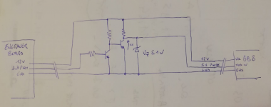
A circuit that I design to level convert 0-3.3v to 0-5.5v is this one.
Works quite well and can be plugged directly "on the wire".

1607331354724.png

On breadboard it works, I have to try it live. Unfortunately there is a small issue because the zero volts are not really zero (but near 60mV) because of Vce.


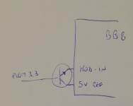
I thought there might also be a solution using the driver's 5V vref, something like this:
1607331678769.png

EDIT: this second schema cannot work!

The driver remains operational without a connected sensor, and this input can also be used as an interlock input: when the input is floating, the driver is on, when shorted - is in standby mode.

Other idea was to short the mod-in to the board 5V Vref to keep it turned on, and then use the PTC connector to modulate the driver, but not knowing the design of the board I cannot understand if it is a technically valid solution (and sufficiently reactive/fast for modulation).
 
Last edited:

94Z28

2
Joined
Jul 1, 2016
Messages
539
Points
43
There are many "industrial" grade logic level shifters out there on eBay, I have ordered several. It can convert the 3.3v to 5v with a small box, powered on the input voltage of 12-24v. Usually an input, and an output. They have them to convert to mA from mV and much more. It could be more reliable than a breadboard circuit. Also, it's nice to have a software developer around here. Where are your beta-testing areas for LaserGRBL? I will try on the Ortur Laser.
 

arkypita

New member
Joined
Dec 6, 2020
Messages
9
Points
3
Hi 94Z28

Thanks for the level shifter hint. I have solved with increasing the current setpoint of my BlackBuck 8M to give 5A when driven with 3.3V PWM signal (as suggested by Shmackitup) and this is enough for me. I just have to be careful not to connect it to a 5V PWM or else I burn the diode!

I use Atomstack, Ortur, and DIY engraver to test my code.

Ortur is a good engraver, but it is somewhat limited by the size of the wiring and connectors.
If you want to use an high-power diode like NUMB44 is better to rewire the supply-to-driver power wiring.
 

arkypita

New member
Joined
Dec 6, 2020
Messages
9
Points
3
PS. my issue with 3.3v board ic logic voltage, is with Ortur. They use STM32 micro that is a 3.3v IC.
 

94Z28

2
Joined
Jul 1, 2016
Messages
539
Points
43
PS. my issue with 3.3v board ic logic voltage, is with Ortur. They use STM32 micro that is a 3.3v IC.
Really? I am working on a Ortur Laser Master 2 for a client and it seems to only operate on 5V but I never read the signal from the controller. Now I will have to.


Top