Welcome to Laser Pointer Forums - discuss green laser pointers, blue laser pointers, and all types of lasers

Buy Site Supporter Role (remove some ads) | LPF Donations

Links below open in new window

FrozenGate by Avery

Beginner Project Help: 488nm laser pointer

junuthun

New member
Joined
May 17, 2020
Messages
4
Points
3
Hello everyone,

I'm new, and I'm very glad to have found this resource. Quick notice: I am not very well versed in electronics, but I do understand the fundamental concepts enough that I thought I could get by (we'll see), and I did try to study youtube tutorials as well as other beginner threads. If I could get any input from anyone for a basic (I think) project, I would really appreciate any help.

*I did invest in protective eyewear prior to starting this project.

For my first project I wanted to assemble a 55mW 488nm pointer, not really building it from scratch as most of it is already assembled. Nothing crazy powerful, although I am well aware of the damage it can cause. I just like the color, and the only practical purpose I want to use it for is stargazing. As I stated before, I am a beginner, but I think it will be gratifying when I am able to finally assemble a laser that works.

Materials:
- Sharp 488nm GH04850B2G 55mW Laser Diode (DTR)
- ACS1500SE 1.5A Buck/Boost Driver (DTR)
- DTR-G-2 Glass Lens W/Focus Ring
- 12mm Copper Module, Full Length, for a 5.6mm laser diode
- Cheap laser housing from a previous mass production laser.

Additional Materials:
- Multimeter
- Soldering Kit

Now for the fun part/ the problem.

I actually purchased the fully assembled 488nm diode module from DTR, so we can safely assume that it was wired correctly and the correct driver was used. This is in part because I was not sure which driver to use with the 488nm 55mW diode, and figured that DTR would use an ideal option. I think I would have attempted building it from individual components if I had known what driver to use.

Anyways, I used the multimeter to try to ensure that I wasn't going to "fry the diode" as I have read so much about already. So, I took two AAA batteries, loaded them into the cheap housing, and measured its voltage and current. (This is probably where it starts to sound cringe-worthy, I really tried to understand it but I'm sure this is where I'm messing up). Current read out around 3.52 Amps or so, and about 2.92 Volts.

I attached the wires from the pre-assembled module to the respective (+) and (-) parts of the housing with batteries, saw a beautiful 488nm color for about 0.2 seconds, and worst of all, I could hear a quiet, high-pitched sound coming from the module right as it flashed the blue light, before it seemed to burn out.

The Driver says it can handle input voltage of 2.9-12V if I'm not mistaken there. Driver output seems to be between 0-1500mA. As I understand it, the driver modifies the input to ensure that the current doesn't exceed 1500mA and overpower the laser diode.

So, is the issue that too many amps were going into the driver? It seems like every youtube video shows someone loading their DIY laser module into either a AAAx2 or AAx2 housing assembly and then proceed to ignite various objects, so I figured I would have been fine, but I was probably foolish to rush into it like that.

If the diode is fried, at least I can try my hand at soldering a new one onto the driver for $30. That sucks, but not the worst price to pay for a learning experience. But on my second go around, I'd really like to get this right, so if anyone is able to help me figure this out, I would really appreciate it.

Thank you!
 
Last edited:


Welcome to the hobby and congrats on the project.

However I see quite a few issues here...

That driver seems to be rated for 1.5A output. That's usually what's used for diodes rated for 1-2W! :eek: That driver was probably overpowering that poor diode ten times more than it needs, instantly frying it.

Also, choosing a real host with a proper power source is just a important as your diode and driver setup. No respectable host ever uses AA or AAA batteries. Furthermore, you can't just cram a module in what I'm assuming is a cheap еBay pen not made to be modified. I mean, what kind of connections does it have? Is it setup for the correct case polarity? Does it have case polarity? Will it even fit a 12mm module? Does it have proper heatsinking for the specific application? What kind of securing system does it have to keep the module in place with proper thermal conductivity? Do you have a picture of it?

This is why I'm not rushing into DIY. You have to have a basic understanding of how to pair a diode to a driver and the relationship between voltage, amps, polarity, and laser power in W or mW, and how it corresponds to what the diode needs and how the driver can supply it.

Even if DTRs shop knows how hook up everything correctly, it's still up to you to pick the correct parts. That's why it's good to do plenty of research and ask questions beforehand.
 
Last edited:
I think at most 100 mA (driver probably outputs 4-6V I'm guessing plz correct me if I am wrong here) is enough to power your 55 mW LD. If you really did feed 1500 mA into it, it is probably fried.

Check your LD's datasheet to determine the correct current, then before installing a new laser calibrate your present driver using a dummy load consisting of a 1 ohm resistor and 5-6 (1N14... series) diodes to make sure it is outputting the correct current at the correct voltage. It'd be nice if you could get an oscilloscope to ensure that the output current doesn't have any recurring spikes, but if the driver is from DTR that probably shouldn't be an issue since its probably well-built.

LDs are incredibly fragile so always use a dummy load before hooking up and frying testing one on your driver.
 
Welcome to the hobby and congrats on the project.

However I see quite a few issues here...

That driver seems to be rated for 1.5A output. That's usually what's used for diodes rated for 1-2W! :eek: That driver was probably overpowering that poor diode ten times more than it needs, instantly frying it.

Also, choosing a real host with a proper power source is just a important as your diode and driver setup. No respectable host ever uses AA or AAA batteries. Furthermore, you can't just cram a module in what I'm assuming is a cheap еBay pen not made to be modified. I mean, what kind of connections does it have? Is it setup for the correct case polarity? Does it have case polarity? Will it even fit a 12mm module? Does it have proper heatsinking for the specific application? What kind of securing system does it have to keep the module in place with proper thermal conductivity? Do you have a picture of it?

This is why I'm not rushing into DIY. You have to have a basic understanding of how to pair a diode to a driver and the relationship between voltage, amps, polarity, and laser power in W or mW, and how it corresponds to what the diode needs and how the driver can supply it.

Even if DTRs shop knows how hook up everything correctly, it's still up to you to pick the correct parts. That's why it's good to do plenty of research and ask questions beforehand.
Lol didn't see your post until after I posted, sorry if I am repeating any of what yours already said!
 
Last edited:
Lol didn't see your post until after I posted, sorry if I am repeating any of what your already said!
I'd just say testing and using a dummy load is redundant in the case of buying pre-set drivers already setup for your diode from DTR as it is already done and setup in a module.

However laser diodes are in fact very very fragile, and should be handled extremely carefully including keeping a eye out for static discharge, which can break your diode.
 
Thank you Snecho and gazer101 for the prompt responses.

I clearly have a lot more to learn.

Furthermore, you can't just cram a module in what I'm assuming is a cheap еBay pen not made to be modified. I mean, what kind of connections does it have? Is it setup for the correct case polarity? Does it have case polarity? Will it even fit a 12mm module? Does it have proper heatsinking for the specific application? What kind of securing system does it have to keep the module in place with proper thermal conductivity? Do you have a picture of it?

Per the host: It's definitely one of those cheap, mass-produced eBay pen hosts. This is in part because I haven't found a reliable source of hosts yet, DTR does not seem to sell any. There seem to be good custom options on the Laser Hosts forum. Mainly, I used this host because it was one I had laying around already.

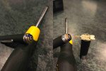
Case polarity is displayed below. I was planning on removing the spring from the hosts original module (pictured on the right, after button was removed) and then soldering it to a push button, and then connecting that to the module. It does fit a 12mm module very nicely. As for proper thermal conductivity, I'm really not sure. Many of the tutorial videos posted in beginner threads on here do not include heatsinks or have much other mention of thermal conductivity. I also figured that the copper housing for the module would adequately mitigate any heat output, unless another layer of insulation is customary.

IMG_0851 (1).jpg

DTR looks like it has a nice heatsink for 12mm modules. But DTR also sells fans and other equipment for very powerful lasers, so I assumed that the heatsink was for 1W+ setups. Most commercial laser pens don't seem to have a 22mm upper half (heatsink) if they're <100mW, or am I looking at an unreliable frame of reference? If it contributes to the longevity of my project, I wouldn't say no to implementing the heatsink. Do 55mW modules get hot enough to warrant a heatsink?


I think at most 100 mA (driver probably outputs 4-6V I'm guessing plz correct me if I am wrong here) is enough to power your 55 mW LD. If you really did feed 1500 mA into it, it is probably fried.

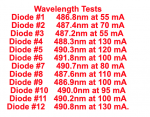
Check your LD's datasheet to determine the correct current

I'm assuming this is what I was supposed to use as a frame of reference 🤦

Screen Shot 2020-05-17 at 11.33.34 AM.png

Yeah, I see now that 1500mA is too much for this diode. These tests are getting upwards of 150mW from this diode, while using <150mA. That's much more powerful than anything I wanted to build. I know these tests are designed to verify the limits of the diode though, so would it be safe to assume that I can create a circuit with <90mA and the diode won't be overly stressed?


Since I most certainly destroyed my diode as a result of that input, do I also have to assume that the driver is damaged? Or is there no easy way to tell?

Once I have a fully functional diode+driver setup again, what should I do to lower the current if the ACS1500SE driver supplies 1500mA? Would it make more sense to use a different driver than the one DTR supplied? Or is this centric around the batteries (2x AAA) being too much input?

Thank you both again for your help. I know I'm apparently in over my head on this one, but I'm still trying to learn and make this work. I'll keep searching other threads to fill the gaps in my understanding in the meantime.

Thanks again.


EDIT:
Additionally, it looks like the ACS1500SE driver is preconfigured by DTR to supply a 100mA output, which should have been safe for this diode correct?
 
Last edited:
I'm confused. You bought the complete DTR module with driver attached right?
All you needed to do is feed a it 3.7V to 4.2V or 2 AAA's.
Why all the Amperage talk if i'm right in assuming you got the complete ready to go DTR module?
You must of shorted it then in using that host. Unless I missed alot because there are alot of reply's and long ones.
Only case positive diodes and modules are the 532's and some 495..

Hi GSS,

Yeah, I purchased the pre-assembled DTR module (driver+diode in a copper housing with lens)

Oh no. So I guess I should not have used the (+) wire on the case while testing, since this is not a case positive diode? I was not aware of that factor, but thank you for the input. Dang.
 
Hi GSS,

Yeah, I purchased the pre-assembled DTR module (driver+diode in a copper housing with lens)

Oh no. So I guess I should not have used the (+) wire on the case while testing, since this is not a case positive diode? I was not aware of that factor, but thank you for the input. Dang.

Send the diode module with diode and driver back to DTR so he can determine if you need a new diode or both the diode and driver and can install them and test so no error occurs there.
DTR is a good guy, maybe will give you a break on the price to repair it as well.
All you then need to do then is supply correctly + and - wires to a power source.
 
Last edited:
Send the diode module with diode and driver back to DTR so he can determine if you need a new diode or both the diode and driver and can install them and test so no error occurs there.
DTR is a good guy, maybe will give you a break on the price to repair it as well.
All you then need to do then is supply correctly + and - wires to a power source.


Hello Encap,

Thanks for the recommendation. I will look into getting into contact with DTR.


So, using two AAA batteries isn't an overly powerful supply that will burn out the diode? Was the issue really that I just used the wrong host since this 488nm diode is incompatible with a case positive host?

I initially thought that the two AAA batteries would be fine, since the driver says it's preconfigured to a 100mA output on DTRs site, and I assumed it would regulate the flow of the current from the batteries. Drivers function partially as modulate-able resistors in that way, right? Or is my understanding of this hilariously incorrect? And the two AAA batteries were within the parameters of the input voltage (2.92V I think).
I was thinking that the driver was set to output too much current. Does the driver have a potentiometer you can turn on it?
 
I was thinking that the driver was set to output too much current. Does the driver have a potentiometer you can turn on it?

The ACS1500SE driver from DTR says, "The drivers are delivered fully tested and preconfigured for 100mA output""
Additionally when DTR sells a module with diode and driver everything is correctly configured and tested before it goes out.
 
The ACS1500SE driver from DTR says, "The drivers are delivered fully tested and preconfigured for 100mA output""
Additionally when DTR sells a module with diode and driver everything is correctly configured and tested before it goes out.
Hmm, if that's the case then it would appear the OP is in for a refund
 
Hmm, if that's the case then it would appear the OP is in for a refund
Not if it was burned out by reversing the polarity of power source to driver as was mentioned in above posts however DTR is pretty good about people making first time mistakes and may replace it anyway at no charge other than maybe shipping which is why I said send it to DTR for replacement and testing of diode or both diode and driver if both were damaged
Whatever the situation may be, starting off with a fresh and tested module, diode and driver combo from DTR is the way to go---nothing more to do but figure out positive and negative of the power source.
 
Last edited:
Is it normal for this module (Sharp 55mw 12mm w/driver) to get really, really hot ? I have a few other random size/power modules and none get even close to this hot. I tried with different battery sizes and types but it still gets too hot to hold for more than a minute, even in my dead fingers. Why so hot ?
 
Not if it was burned out by reversing the polarity of power source to driver as was mentioned in above posts however DTR is pretty good about people making first time mistakes and may replace it anyway at no charge other than maybe shipping which is why I said send it to DTR for replacement and testing of diode or both diode and driver if both were damaged
Whatever the situation may be, starting off with a fresh and tested module, diode and driver combo from DTR is the way to go---nothing more to do but figure out positive and negative of the power source.
Doesn't sound like reverse polarity since the diode actually lit up, Just sounds like another case of these drivers really don't like to boost at all, I've tested both the 500SE and 1500SE for this reason and have determined that an extremely undersized inductor for the job is the issue for both drivers. When I modified them with an appropriate 6.8uH 3.6A Isat inductor from Panasonic they, for the most part, stopped having such glaring issues because as you know a draw of a couple of amps is not at all normal when driving such diode. I have observed this too, When driving a low-power single-mode 455 the drivers before the inductor mod drew a couple of amps but then after it, they drew a more appropriate couple hundred milliamps, As you can tell the overheating issues were mostly gone but they did run hot, just took a while for them to heat up.


Back
Top