Welcome to Laser Pointer Forums - discuss green laser pointers, blue laser pointers, and all types of lasers

LPF Donation via Stripe | LPF Donation - Other Methods

Links below open in new window

ArcticMyst Security by Avery

Beginner needs help with laser driver replacement

Johnny_3d

New member
Joined
Feb 2, 2021
Messages
7
Points
1
Hi,
I'm from Germany, 17 years old and I'm glad to found this forum :)
I have some experience with electronics and lasers and know the basics.
However, I bought an RGB show laser from 2006. Unfortunately, the red laser driver does not work anymore and the green driver powers randomly when not receiving any signal (safety switch turned to OFF!). I found no way to repair the PCBs.
I don't know the power of the blue and red laser, since the laser is some type of Noname product. (The green laser says "G150" - 150mw?).
Furthermore, the red and green laser (probably dpss) drivers have 8 output pins (TE+, TE-, TS1, TS2 (I still don't know for what these four are) and of course FN+, FN-, LD+, LD-).

Where can I get this type of laser driver? I found only this online: bit.ly/2NPHwos (shortened URL; I need to post 20 posts to share a LINK???)
The green laser output has 8 pins. Could I just use this diode driver for my green dpss laser and a second one for my red dpss laser? Or would you recommend another driver?

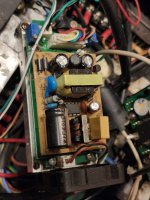
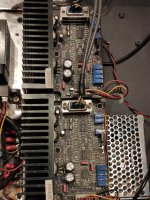
That's my red laser driver (green and blue are different ones):
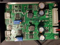
WhatsApp Image 2021-02-02 at 10.44.16.jpeg


Joined
Jun 22, 2016
Messages
2,686
Points
113
I highly doubt red / blue are DPSS, but most likely the green is DPSS..
Can you post any information or RGB showlaser unit itself?

EDIT:
More images inside of unit would be great too

FN -/+ are probably for fan
LD -/+ are driver output for Laser diode / module
and my guess for TE -/+ are TTL signal input (usually 5V) or it can be temperature control (for fan) , can't say for sure > look where those wires goes / ends
 
Last edited:

Johnny_3d

New member
Joined
Feb 2, 2021
Messages
7
Points
1
The 8 right pins are output. "+PM-" is input (left side)

I don't know a lot about the laser:
- It's probably from 2006
- written on it is "COLOR CANNON 300"
- The system was already modified by someone before me (hard to tell which part is original and which not)
- none of the PCBs has useful information marked
- It has ILDA, DMX, and a simple test function, where a "W" is displayed
- green laser has 150mw
- TTL

Here are some more pictures:

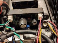
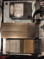
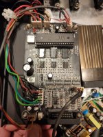
WhatsApp Image 2021-02-02 at 12.21.45 (1).jpeg Driver Green

WhatsApp Image 2021-02-02 at 12.21.45 (2).jpeg Driver Blue

WhatsApp Image 2021-02-02 at 12.21.45 (3).jpeg Lasers

WhatsApp Image 2021-02-02 at 12.21.45 (4).jpeg Mainboard

WhatsApp Image 2021-02-02 at 12.21.45.jpeg Drivers Galvo X/Y
 
Last edited:

Johnny_3d

New member
Joined
Feb 2, 2021
Messages
7
Points
1
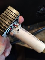
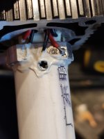
The laser is glued and I don't want to risk destroying it.

WhatsApp Image 2021-02-02 at 13.41.49.jpeg


I also found a hidden sticker on the red laser: 650nm and "R500" (->500mw)
So I only have to adjust the current, not the voltage?
Simular laser diodes (635nm; 500mw) are sold with "operating current: 500 - 800mA" and "operating voltage: 1.9 - 2.6V" so I would refer to them.
EDIT:
Does the laser get damaged if it runs with too high current? How do I measure the current on the board without the laser connected?
 
Last edited:
Joined
Jun 22, 2016
Messages
2,686
Points
113
Yes, driving it too much current will fry your laser.
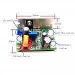
You will need a "dummy-load" and multimeter. Output current is adjustable by the trimmer resistor (blue trimmer box on PCB).

s-l1600 (11).jpg

If you are unsure you can always buy module+driver >>
but you'll need to align the laser after that.


Can you post more images of that red module?
 
Last edited:

Johnny_3d

New member
Joined
Feb 2, 2021
Messages
7
Points
1
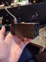
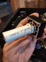
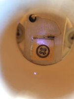
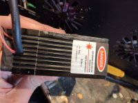
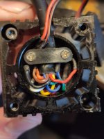
WhatsApp Image 2021-02-02 at 16.06.12.jpegWhatsApp Image 2021-02-02 at 16.06.13 (1).jpegWhatsApp Image 2021-02-02 at 16.06.13.jpeg

WhatsApp Image 2021-02-02 at 16.06.14 (1).jpegWhatsApp Image 2021-02-02 at 16.06.14 (2).jpegWhatsApp Image 2021-02-02 at 16.06.14.jpeg

I'm very thankful you helping me, thank you :)

I don't really understand why I need a dummy with a constant power supply. Couldn't I just lower the current to a very low value and then connect the laser and turn it up to 500mA again?

I will probably order this RGB Driver, so I can fix the issue with the green laser as well: ebay.to/39Cisd8 (shortened again, just copy and paste)
 

Johnny_3d

New member
Joined
Feb 2, 2021
Messages
7
Points
1
The driver has 0V output on the pins FN+/- and 0V output on LD+/-.
But FN+ and 12V- connected are about 12V
and LD+ and 12V- connected are about 3V.
- So, yes :/

How did you find the laser diode?
I think will order the RGB board I send earlier, not the whole laser.
 
Last edited:
Joined
Jun 22, 2016
Messages
2,686
Points
113
It is pretty old diode :D
I highly recommend to get newer module & driver
Those old C-mount diodes are known to be a brittle and you can't control red module TEC with that RGB driver
 
Last edited:

Johnny_3d

New member
Joined
Feb 2, 2021
Messages
7
Points
1
I can control the TEC with the single driver board neither. Does it matter?
 

Johnny_3d

New member
Joined
Feb 2, 2021
Messages
7
Points
1
Uhm, I only paid 70€ for this whole laser system and it wouldn't make sence investing a lot in it.


Top