LPF Donation via Stripe | LPF Donation - Other Methods
Links below open in new window
ArcticMyst Security by Avery


You are using an out of date browser. It may not display this or other websites correctly.
You should upgrade or use an alternative browser.
You should upgrade or use an alternative browser.
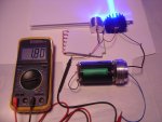
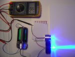
Beam combiner tests (new battery-driver holder)
- Thread starter laserluke
- Start date
- Status
- Not open for further replies.


T_Warne
0
- Joined
- Jan 18, 2009
- Messages
- 1,443
- Points
- 83
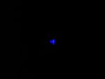
How small a head will you be able to get the lasers and optics into? I don't know if you are going to keep the diodes oriented as they are now, but I like the + look of the dot.
Last edited:
- Joined
- Mar 18, 2012
- Messages
- 173
- Points
- 0
Into how small a head will you be able to get the lasers and optics? I don't know if you are going to keep the diodes oriented as they are now, but I like the + look of the dot.
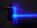
The optical head diameter is 5cm. It protrudes of about 4.5cm to the top of the battery-driver holder.
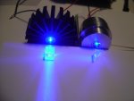
The shape of the beam dot and diodes orientation is mandatory because of the light polarization. With an anamorphic prism pair after each diode you can obtain a round dot, but with some power loss and increased dimensions and costs.
- Joined
- Dec 27, 2011
- Messages
- 2,062
- Points
- 48
I am loving this - I think taking two 445's and making a + dot is an awesome idea.
- Joined
- Sep 12, 2007
- Messages
- 9,399
- Points
- 113
...since you're not trying to clump them over one another...
But... that's exactly what's happening here.:can:
- Joined
- Mar 18, 2012
- Messages
- 173
- Points
- 0
I am loving this - I think taking two 445's and making a + dot is an awesome idea.
This pbs cube is very efficient, the output power is close to twice the power of a single diode.
The driver can easily power up a couple of new 9mm diodes. The output power could be more than 6W... a very powerful + dot :yh:
Benm
0
- Joined
- Aug 16, 2007
- Messages
- 7,896
- Points
- 113
What would be the benefit of the + shaped output?
If you get two - shaped outputs superimposed you can still use prism pair optics to get a somewhat decent beam, but that option is clearly out ofter combining the beams this way.
Combining two - shaped beams with a pbs would require a quarter wave delay in one of the source beams to rotate the polarization by 90 degrees, but i stilll think that would be the better way to go - unless you wanted to project + signs for some reason.
- Joined
- Mar 18, 2012
- Messages
- 173
- Points
- 0
What would be the benefit of the + shaped output?
If you get two - shaped outputs superimposed you can still use prism pair optics to get a somewhat decent beam, but that option is clearly out ofter combining the beams this way.
Combining two - shaped beams with a pbs would require a quarter wave delay in one of the source beams to rotate the polarization by 90 degrees, but i stilll think that would be the better way to go - unless you wanted to project + signs for some reason.
You are right, but to follow your suggestion you need the quarter wave delay and the prism pair and so power loss, more complex optical head etc.
If you want you can also use a prism pair after each diode to obtain the same result with components without narrow bandwith.
At the end the simply question is: do you want only optical power or a circular dot?
If you need power to burn or even to pump doped materials like fluoride glasses the dot shape it's not so important.
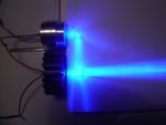
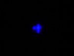
And moreover... at even 2W it's very difficult to clearly see the dot shape with naked eyes because of its terrible brightness...
T_Warne
0
- Joined
- Jan 18, 2009
- Messages
- 1,443
- Points
- 83
I just like the cool + target reticule look.
- Joined
- Sep 12, 2007
- Messages
- 9,399
- Points
- 113
At least this time you are not using your usual language.
Welcome to the internet.

Last edited:
ARG
0
- Joined
- Feb 27, 2011
- Messages
- 6,772
- Points
- 113
How much power is being lost to the optics?
- Joined
- Mar 30, 2011
- Messages
- 174
- Points
- 18
Nice! Looks like you could stuff this into a maglight... just drill two holes for diodes.
")
- Joined
- Mar 18, 2012
- Messages
- 173
- Points
- 0
How much power is being lost to the optics?
This setup is very imprecise because it's only a proof of concept. You need to block a diode and rotate the other until you find the minimum power at a direction and the maximum at that perpendicular. You must then repeat this procedure at inverse for the other diode. I have only a too approximative measure at this stage and i'm completing the optical head. I'll post the correct results.
- Joined
- Sep 12, 2007
- Messages
- 9,399
- Points
- 113
You need to block a diode and rotate the other until you find the minimum power at a direction and the maximum at that perpendicular.
That's the slow way of doing it.
Laser diodes are polarized along the plane of their PN junction. The beam profile is an image of the junction. Therefore, if you have one beam profile at 90° from the other beam profile, their polarizations will also be 90° from each other and will sum with the greatest efficiency. No power measurements required.
It's not a coincidence you got a + pattern.
- Status
- Not open for further replies.
