Welcome to Laser Pointer Forums - discuss green laser pointers, blue laser pointers, and all types of lasers

LPF Donation via Stripe | LPF Donation - Other Methods

Links below open in new window

ArcticMyst Security by Avery

Argon Laser Pulse tester

Joined
Feb 2, 2012
Messages
577
Points
43
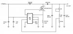
I am building an Argon Laser Pulse Tester based on the Professors Argon Design. The Professor's Homebuilt Lasers Site - Argon Lasers

Stage one is a transformer for the fillament. In Australia we have 240 Volts which I could not find a suitable transformer to use for the fillament. No problem. Just modify a 240 Volt Toroid transformer.

I bought an 80 va 240 Vac to 2 x 12 Vac Toroid. Plenty big enough for a fillament supply.

Remove the outer layers of insulation.

Remove the secondary windings. Carefull not to damage anything.

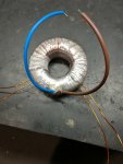
Wound about 10 turns of 1mm insulated wire on the transformer so I can measure and calculate how many turns I would need. Comes out to be 13 Turns for each of the 1.55 Vac windings.

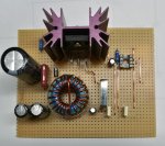
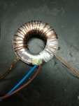
Wound 2 windings of 15 AWG cable onto the transformer. 13 Turnes each.

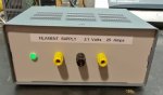
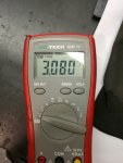
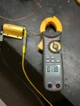
Time for some testing. I have a 0.22 Ohm 100 Watt resistor to use for the test. Fired it up. 13.8 Amps at 3.08 Volts. Almost perfect. The manual for the JSDU Power supply states it should be 3.1 Volts +/- 0.2 Volts.

Reinstall all the insulation on the transformer.

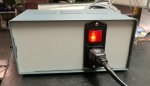
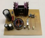
Here are the Pics so far of the Fillament transformer and the test shots.

I will keep this thread updated as I build it.
 

Attachments

  • IMG_20170502_183811.jpg
    IMG_20170502_183811.jpg
    81.7 KB · Views: 61
  • IMG_20170502_183805.jpg
    IMG_20170502_183805.jpg
    92.4 KB · Views: 57
  • IMG_20170502_183835.jpg
    IMG_20170502_183835.jpg
    98.4 KB · Views: 112
  • IMG_20170502_190040.jpg
    IMG_20170502_190040.jpg
    89.1 KB · Views: 50
Last edited:


diachi

0
Joined
Feb 22, 2008
Messages
9,700
Points
113
Looking forward to more, hopefully you can get this figured out! Looks like you know a fair bit about electronics, that'll make life easier. :)
 
Joined
Feb 2, 2012
Messages
577
Points
43
Looking forward to more, hopefully you can get this figured out! Looks like you know a fair bit about electronics, that'll make life easier. :)

If nothing else it's some fun building it. I am not up to date with modern electronics though. I started my electrical / electronic career over 35 years ago.

At least I will be able to control the voltage on the Anode and find out when / if the tube draws current. I can put a shunt in the center tap of the fillament supply and look at the current with my CRO. It will be much easier to check things with a pulse supply.

I will be increasing the triggering voltage. The one in the JDSU supply would peak around 5 Kv. I will aim for 10 Kv.

According to the professor it should lase if the pulse is longer than 0.5 mS. I am using the biggest cap he tested to ensure a longer pulse. Should be about 2 mS. It should be visable as a fast cyan pulse.

Still unsure about were to place the trigger cct. Normaly they are close to the Anode of the tube. I am considering a bit further away but I will need some 10 Kv cable to connect it.
 
Last edited:
Joined
Sep 12, 2007
Messages
9,399
Points
113
I will need some 10 Kv cable to connect it.

Nah. You really don't. Not for a test rig.

Cable dielectric strength is very conservatively rated. I made custom electrical cable for a few years. 600V UL/CSA rating gets a dielectric withstand test of 6kV high frequency AC (up to 17kv P-P) in a spark tester. Since this is a mere 2ms pulse, the insulation will be fine, especially if you keep it away from other conductors if possible to use some of the air dielectric strength.
 
Joined
Sep 20, 2013
Messages
17,424
Points
113
Insulated wire is conservatively rated, but if you have access to some older CRT televisions, you can get some very good HV insulated wire. As long as you keep it away from grounded sources and the like, you should have no problems with arc-over even if you can't access HV wire.
 
Joined
Feb 2, 2012
Messages
577
Points
43
Their was a time when EHT leads from a TV were all over the place. Been so long since i have even seen a CRT TV or monitor.

Another thing. The Lead also carries the Anode current. It needs to carry a 10A + Pulse. Although, for a pluse test it's probably not very important. Some voltage drop wont effect this test.


Interesting about low pressure. I havn't read much about the symptons of low pressure other than very low. Then no Purple Glow is seen with a trigger pulse. If it is low pressure leaving it a while it might be able to start for a short time again.
 
Joined
Feb 2, 2012
Messages
577
Points
43
I had some time at work tonight to finish off the Filament Power Supply. Looks safe, and pretty now.


Next I will wind the Trigger Transformer. Pretty straight forward.

I have been doing some thinking about the Supply for the Anode Pulse. I am leaning towards a 12 VDC Boost Circuit with variable output. 100-350 VDC. It only needs to charge the Pulse Capacitor up so I don't need much current. This will be much safer than using a Variac on the mains. And more fun :)
 

Attachments

  • IMG_20170504_195155.jpg
    IMG_20170504_195155.jpg
    96.6 KB · Views: 95
  • IMG_20170504_195126.jpg
    IMG_20170504_195126.jpg
    105.7 KB · Views: 81
Last edited:
Joined
Sep 20, 2013
Messages
17,424
Points
113
Looks like you spent a lot of time setting up this test circuit. It looks great, but isn't it just for testing this one tube?
 
Joined
Feb 2, 2012
Messages
577
Points
43
Looks like you spent a lot of time setting up this test circuit. It looks great, but isn't it just for testing this one tube?


It does get boring at work sometimes :) Most of the fun is building the test unit. I don't build much electronics anymore. I used to build a lot of junk just for fun. Maybe two tubes if the one on Ebay ever gets shipped.

Also, I don't know were this will lead. Maybe I will need to build a full power supply for the tube. At least the Filament supply is up to that level.
 
Last edited:
Joined
Feb 2, 2012
Messages
577
Points
43
I have drawn up the circuit I will be using to supply the variable voltage to the Pulse Circuit. It won't supply much current but it doesn't need to. All it does is charge up the cap to the test volage.

Most parts should be here tomorrow except the MAX1771 which is an order in part.
 

Attachments

  • MAX1771SMPS.jpg
    MAX1771SMPS.jpg
    41 KB · Views: 193
Last edited:
Joined
Sep 20, 2013
Messages
17,424
Points
113
I'm a little confused. I thought the test circuit was completed and finished. Did you decide to change things around?
 
Joined
Feb 2, 2012
Messages
577
Points
43
Some more free time at work :)

Assembled the 12v boost board. This will give me an adjustable output from 100 to 400 vdc to charge the Capacitor used for the pulse test. I chose this way as it's much safer than using a Variac on the mains.

I can't test it yet. The MAX1771 is a few days delivery.
 

Attachments

  • IMG_20170510_182305.jpg
    IMG_20170510_182305.jpg
    153.2 KB · Views: 67
  • IMG_20170510_182311.jpg
    IMG_20170510_182311.jpg
    133.3 KB · Views: 49

diachi

0
Joined
Feb 22, 2008
Messages
9,700
Points
113
Some more free time at work :)

Assembled the 12v boost board. This will give me an adjustable output from 100 to 400 vdc to charge the Capacitor used for the pulse test. I chose this way as it's much safer than using a Variac on the mains.

I can't test it yet. The MAX1771 is a few days delivery.


Looking good! :)
 
Joined
Feb 2, 2012
Messages
577
Points
43
The MAX1771 arrived.

Got myself in a bit of a mess with this boost circuit. Some times simple circuits dont do what you expect. Using a MAX1771 might not have been a good idea. Like others I have problems with it. Works ok set to min about 108 volts. When I try to increase the output voltage it goes crazy. Straight up to 430 volts and wont regulate. From what i have now found this boost regulator suffers from noise and doesnt do what is expected. Its not turning the pulse off and output rises to the max with a 25k load. The feedback is supposed to switch the pulse off when it rises to 1.5 volts. On my CRO the feedback is rising to 5 volts and it doesnt switch the pulse off.

Switch mode is bad enough with noise. My layout is more than likely the problem. High frequency pulses all over the place :)

Need to think about my next move. I realy do want the pulse tester isolated from the mains for safety reasons. I have seen some other simple boost circuits using a 555 timer and comparator just for charging a Cap to a set voltage.

I am an analogue guy from the old days. Should stick to what i know :)
 
Last edited:


Top