Welcome to Laser Pointer Forums - discuss green laser pointers, blue laser pointers, and all types of lasers

LPF Donation via Stripe | LPF Donation - Other Methods

Links below open in new window

ArcticMyst Security by Avery

5x GH04W10A2GC in a Maglite

Joined
Feb 12, 2016
Messages
589
Points
63
Yes, me too always wanted to make a focused burner like this one:


but regarding how much it would consume with all NUBM44 diodes I have first tought to build a smaller similar thing with lower consuming 405nm diodes.
The original idea was to try with BDR-209 single modes because of the high power density in the SM beams but orientation of the beams in the DTR modules was far from constant. This should be due to the fact that it is very difficult to press 3.8mm LD into the barrel keeping it exactly straight. However, with bigger bodies of 5.6 and 9mm LDs this should be easier.

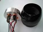
I also noticed that the 1" PCX lens from Thorlabs enters well into the maglite head what means that there is no need to do a special adapter. Only adapter I had to make was an Al HS plate to hold 5x 12mm DTR modules. More than 5 would not pass into magite head and if I would add another module into the center like in this video, then I do not get how the heat from this one would go out!

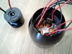
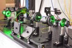
Once I have received the cylinder from CNC shop (dimentions: 48.25x15mm) I inserted 2 modules with BDR-209 and 2 modules with new Sharp GH04W10A2GC diodes (all with new G-8 collimators) and tried to focus them into one point with Thorlabs lens. The beams from BDR-209 never came to the common point but the beams from Sharp LDs did combine pretty close into one point.

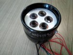
After this I purchased 3 more Sharp diodes with drivers from DTR and tried focusing with 5 Sharp LDs with DTR G-8 collimators installed with drivers connected in parallel. Well, this was not perfectly one point but all 5 spots could fit into a 3x3mm square.

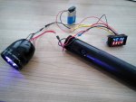
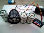
I also modified the switch a little and first tried to feed these drivers with 4, then 6 and 7 Energizer D cells as the Maglite body was made for them. But even with 6 and 7 D cells (I have 2D and 4D maglites with 2D and 1D extensions so can do any combination) the total voltage fell from 9V to 4 - 4.7V at 3.3A drain.

The way to increase voltage was to apply SAFT Li-SOCl2 cells which are found on ebay in D size. But when I tried 2 of these cells, I found that the maximum current they could afford was 1A only!
Luckily, these are also produced as LSH 20 model with maximum drain of 4A in spec sheet. So, when I tried 2 of these the current reached 4A but the voltage fell from 7.2 to 3.9V at this current drain (and one of batteries made some smell of sulfur after trial!!!).
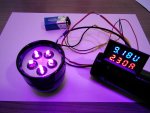
Finally, added 3rd cell and now the voltage keeps at 9.2V at 2.3A drain what seems reasonable for 5 of these drivers connected in parallel... No more smell, no sound, a lot of violet light!
 

Attachments

  • 1- 2xSharp + 2xBDR.jpg
    1- 2xSharp + 2xBDR.jpg
    470.1 KB · Views: 24
  • 2- 5xSharp.jpg
    2- 5xSharp.jpg
    575.3 KB · Views: 23
  • 3- 5xG-8.jpg
    3- 5xG-8.jpg
    589.2 KB · Views: 21
  • 4- 6D cells 13W.jpg
    4- 6D cells 13W.jpg
    600.9 KB · Views: 23
  • 5- 3x LSH20 cells.jpg
    5- 3x LSH20 cells.jpg
    541 KB · Views: 27
  • 6- 21W.jpg
    6- 21W.jpg
    589.4 KB · Views: 29


Joined
Feb 25, 2010
Messages
1,643
Points
113
VERY NICE !!!!!!!!!

MMMMM ?????

What do you measure the combined output. ???

Thanx.....CDBeam
 
Joined
Feb 12, 2016
Messages
589
Points
63
I measured it now (a little out of focus not to burn the LPM sensor) and it is 4.8-4.9W in total. DTR sets the drivers to produce 1W+ with G-2 and 0.9W+ with G-8, so this looks reasonable for 5 beams.
I thought about turning the driver pots to output 1.5W each module but then it would drain batteries more again and I will have to add 4th one to keep the voltage up... And I did not add HS for drivers (it could be possible), so I max. kept the thing on for 30 sec up to now when I felt drivers heat by tough.

I also checked these DTR modules with ACS1500SE drivers and found that they heat least if the input voltage is 4.5-5.5V (maybe they just convert overvoltage into heat - so are not very energy savy?) but it is not easy to obtain an equilibrium at this value when the current should be high enough...

Bad that the points do not coinside at focus - they are super small. I do not get how the guy in video could have them into 1 point regarding he has smaller modules. Maybe the whole piece in his bezel is just a CNC made multimodule? Or he has all NUBM44 when spot sizes are greater than any beam shift by misalignment?
 
Joined
Feb 25, 2010
Messages
1,643
Points
113
Reactions:HMMMMMmmmm…..Maybe a Blue Diode unit......patterned after the Green Gargoyle design !!!!

This hobby will continue to cost me a ton of money !!!....and....will lead me to eat Cat Food in my retirement years !!!! YUM !!!!!

CDBeam
 
Joined
Feb 12, 2016
Messages
589
Points
63
I also think that the focusing problem here is due to diodes pressing into the DTR modules. In this way each of them is not exactly perpendicular to the surface. If they were just held with caps like in more professional square Lasertack or LSP housings (what you for sure will be using in Gargoyle), the beams should have been more parallel and focus tighter.

Would you agree with that?
 
Joined
Jul 10, 2015
Messages
9,908
Points
113
Lens barrel thread slack is an issue, you need to use an inside threaded sleeve or the end of another empty copper module to lock down each primary lens focus and adjust the runout ( side to side play ) so all your beams run parallel.

Another way is to make each module adjustable, in this old build I drilled a hole in the side of each back half for my wires and used a machine screw through the back of each module and washer/nut at the 2nd plate to adjust each beam so they all run parallel, my front plate was 3/8 inch thick aluminum wallowed out slightly to facilitate adjustment with set screws at an angle to hold each tight.

Point is you need to build in adjustability to trim out your beams, you can't count of everything lining up, but lens barrel thread slack is also a reason for misalignment, more so that diode seating in many cases.

0426080117.jpg
 
Joined
Feb 25, 2010
Messages
1,643
Points
113
RC / LSG...YES !!! I am not a fan of the LD to be pressed into modules !!! Just a slight off-axis pressing....and....well...you are stuck with this condition !! THIS is why I always open up the seat....ever so slightly....to achieve a friction fit....not a pressed fit !!

Now....someone may say...."WHOOOOaaa….Buddy....Does a friction fit do as good a job at thermal transfer as a pressed fit ?????".....NO, it does not !...I imagine a pressed fit has a slight thermal transfer advantage....but then....what good does that do....if your beam is crooked ???? None !!

For single LD builds....A pressed fit is no problem at all....for one cannot really discern the off-axis condition between the beam path and the build axis.....BUT.....when we venture into the..." World of Combiners "....Multi LD builds....this is when this problem rears its ugly head !!!!

Adjustability is not optional....it is demanded for Combiner builds !!! Trust me....I have had many, many hours spent....fighting alignment issues !!
One must have the ability to compensate !!!

OK...YES....with the condition of adjustability.....naturally comes the possibility of near perfect alignment....becoming....screwed up....out of alignment.....well.....that is just the cost of adjustability.....I must be able to attain initial near perfect alignment.....any other path is folly !!

As for the issue with Collimation Lens barrel slack.....Hmmmm I do not know why this condition exists....but it does. SO...I always use a strip of Teflon tape between the Lens Barrel and the Mount !!! Secures the fit and keeps dust away from the LD window !!!!

Just some observations….made possible over the years thru trial and error, the support of LPF and clients !!!.....

Later,
CDBeam
 
Joined
Feb 12, 2016
Messages
589
Points
63
Yes, Bob and RC, you are completely right. It should be this why more expensive LD housings just keep LD in place by friction of a tap with 4 screws, and are not made for pressing into copper hole like Aixiz modules. But adding something what would adjust barrels as well - seems to difficult to me.

With my Maglite 405nm Sharps already pressed into DTR modules I can only try to rotate modules a little, maybe so I could find a position to make focuses closer... They all are only 1mm2 small, so almost 5W would be a funny burner...

BTW this misalignment is also the case with LDs factory pressed into NUBM08 and NUBM44 blocks.
Lately I was designing a thing to make all the outcoming beams perfectly parallel.
And this thing will be called - DMD chip!

A big macro DMD chip which will have 16 kinematic mirrors 2D adjustable by screws (still not sure if this can work since it might need M1.5 screws or even smaller). Positioned similar to this model:

 
Joined
Feb 25, 2010
Messages
1,643
Points
113
The basic problem is...we are trying to achieve near perfect Parallel alignment....in a Hand Held unit !!! See the attached pic of a Lab Optical Table !! We are attempting to do some of the Optical manipulations done on a set up like this...in an area the size of an egg !!! No wonder we are driven to madness !!!

I must note....that the use of any bounce mirror provides the ability of beam steering....pitch and yaw adjustability. However....even with a bounce mirror, we still must achieve optimal X-Y alignment of the Laser diode itself.

I find it curiously interesting.....that even a Full Block of NUBM08 or NUBM44 array has the off axis condition ...Why should this be ??? MMMMmmmmm…..???? Maybe.....this phenomena presents...because...the diodes themselves have manufacturing variability !! ( What I call the Igor State...haha...See the pic of Marty Feldman )….The beam axis is not perpendicular to the LD case.....and that is why all the beams are not parallel.

I speculate....we are fighting this condition ( Igor State ) when we enter the " World of Combiners "......So it goes. Not many venture into Combiners !! They likely read of our trouble....and say..." Nah....Screw that " ...Yea...I can understand that ! The real take away is the information we share to overcome these obstacles !!

And...we have been generally successful in our attempts at alignment. OK...we are not going to be as precise as a Lab Set-up....SO...So what !!! Our cost is 1/1000 their cost....and likely we achieve 90 % of their precision...and we do this Optical manipulation....on a Hand Held size !! I can accept these trade-offs !!!

CDBeam
 

Attachments

  • Marty Feldman_ Cross Eyes 1.jpg
    Marty Feldman_ Cross Eyes 1.jpg
    22.1 KB · Views: 7
  • Laser Optical Table.jpg
    Laser Optical Table.jpg
    164.1 KB · Views: 7
Last edited:


Top