Welcome to Laser Pointer Forums - discuss green laser pointers, blue laser pointers, and all types of lasers

LPF Donation via Stripe | LPF Donation - Other Methods

Links below open in new window

ArcticMyst Security by Avery

3V input driver DIY

Status
Not open for further replies.

phenol

0
Joined
Oct 30, 2007
Messages
533
Points
18
:eek: :-X
hopefully someone can show that 15-volt "burst of energy" from an unused for awhile 1.5-v battery on a scope.
anyone? ....


woop

0
Joined
Nov 9, 2007
Messages
342
Points
0
if it did exist, cheap laser pointers would blow the first time you use them.
batteries are not capacitors, they only make the voltage possible in the chemical reaction they use, a little more or less depending on the concentrations and stuff...
maybe when someone tried to measure the 'effect' they actually captured static from their own bodies, or something.
 
Joined
Feb 5, 2008
Messages
6,252
Points
83
Hey, 'bout that link, it's only a link to forum where is a link to buy a driver.
I don't want to buy anything, ok

I just want to assemble a small laser driver that can run off couple AA batteries, and it's small enough to fit in some flashlight.

Scheme, anybody?
 

woop

0
Joined
Nov 9, 2007
Messages
342
Points
0
the idea of the amc thing is that you buy a LED driver, take one of the chips off the board and use it to drive a laser at 340mA
i don't think it would work with 2AA's though. you will need at least 3.3V
the only way you are going to drive a burner off 2AA's is with a switching power supply, a boost driver.
i have personally made 3 such circuits
one to drive anything, its a boost/buck (sepec) design, works off 2AA's or more
http://www.laserpointerforums.com/forums/YaBB.pl?num=1194375801/168#172
one that drives bluerays, or anything with a forward voltage above 3v. its boost only and really small
http://www.laserpointerforums.com/forums/YaBB.pl?num=1209911140#0
i just made one with a different chip, it works off a single AA or more and drives anything, but it will only supply 300mA with 1 AA. its also really small
http://www.laserpointerforums.com/forums/YaBB.pl?num=1212653254/24#31

the last driver is the best. its buck/boost and it is really small and has less parts

all the drivers i made so far suffer the same problem as the AMC, the ground of the laser can't be connected to the ground of the battery, so you can't use a metal case and let the laser body (if its connected to the - pin of the diode) touch the case.
this can be fixed with a few more parts though

alternatively you can buy the DrLava driver
 
Joined
Feb 5, 2008
Messages
6,252
Points
83
That's exactly what I was looking for, that last one you say it can run off one AA batt.
But, the thing is, I can't read the schematics, I don't have an etchant and all that sh't,

Please can you post the schematic in standard simbols?

I would greatly appreciate it!
 

woop

0
Joined
Nov 9, 2007
Messages
342
Points
0
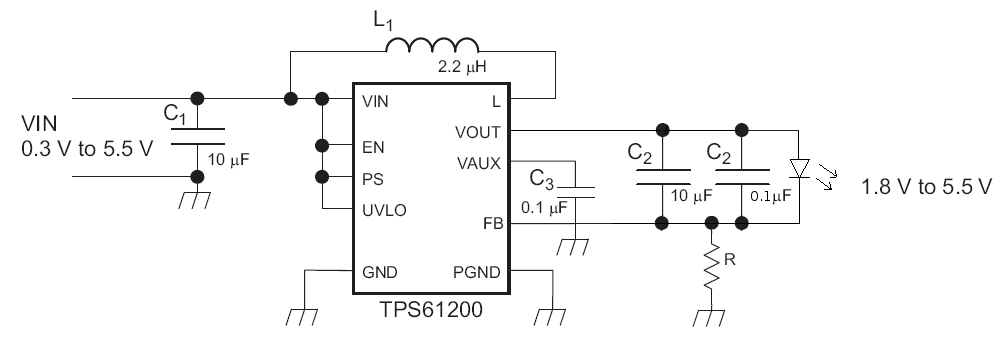
i posted it in that other thread, but here it is again.
the question is, do you understand how it regulates the current?
the voltage across the resistor will equal the current times the resistance.
and because the feedback reference voltage is 0.5V, the driver will apply more voltage (and thus current) until the voltage across the resistor is 0.5V
I am thinking of offering these boards with the IC's pre soldered (because they are the hardest part to solder)
and maybe full working boards too.

woopschem.png
 
Joined
Feb 5, 2008
Messages
6,252
Points
83
Thank you for scheme, I will try making one :)
Just how exactly did you manage to make it so small :-?

You must be the pro, right?
Anyway, the only resistor down there is the pot, correct?
 

woop

0
Joined
Nov 9, 2007
Messages
342
Points
0
Eudaimonium said:
Thank you for scheme, I will try making one :)
Just how exactly did you manage to make it so small :-?

You must be the pro, right?
Anyway, the only resistor down there is the pot, correct?

the current in that schematic is set by the resistor, but it should't be a pot because that resistor has all the current from the LD flowing through it.
it should be a smd resistor, or 2 in series/parallel to get the right value.
the value of the resistor is R=0.5/I

and how did i make it so small? I just played around with the layout until I was satisfied
 

airy52

0
Joined
Jun 14, 2008
Messages
231
Points
0
woop you are posting schematics to the tps61200. but in that last link in your 3-link post, its a schematic with the 01 not the 00. which is for non adjustable fixed constant voltage.


just makin sure this goes smooth, dont want you ordering the wrong parts. good luck, and search around this section of the forum more, there are currently a lot of new drivers being developed. :D
 

woop

0
Joined
Nov 9, 2007
Messages
342
Points
0
oh yeah. oops. i just edited that post so as not to confuse people
 
Joined
Feb 5, 2008
Messages
6,252
Points
83
Ey, all these capacitors, really small ones can be found in dvd friers, right?

But, how do I know the value? Nothing written on them,
somebody, heLP!
How can I tell the capacity of these tiny capacitors?
 

woop

0
Joined
Nov 9, 2007
Messages
342
Points
0
Eudaimonium said:
Ey, all these capacitors, really small ones can be found in dvd friers, right?

But, how do I know the value? Nothing written on them,
somebody, heLP!
How can I tell the capacity of these tiny capacitors?
you measure them with a capacitance measuring DMM :p
turn it to the 20uF setting you are looking for >8uF caps for the input and output filters
 
Joined
Feb 5, 2008
Messages
6,252
Points
83
Hell, I ain't havin that kind of instrument, btw, measuring every one until I find the one I need, that could finish my nerves.

Any other way? They gotta be marked somehow!
 

woop

0
Joined
Nov 9, 2007
Messages
342
Points
0
they are not marked in any way. sometimes the bigger ones don't even have a larger value.
you can use an educated guess, caps that look like they are on a power line might have a larger value.
I just ended up de-soldering heaps of them and measuring them.

you could put the board in an oven at 220C until the solder is melted, then just wipe off all the components. that would be a very efficient way of obtaining components.

you could buy or make some smd tweezers to measure the caps if you find it tedious

multimeters that measure capacitors are pretty cheap
here is one http://www.jaycar.com.au/productVie...d2=&pageNumber=&priceMin=&priceMax=&SUBCATID=
 

viroy

0
Joined
Mar 20, 2008
Messages
126
Points
0
Hi guys, sorry to butt in but i am trying to do something real similar and have nowhere else to turn.
i need to step up 3v to between 7.5v-9v... can this also do that with some modification?
thanks
 
Status
Not open for further replies.


Top