Welcome to Laser Pointer Forums - discuss green laser pointers, blue laser pointers, and all types of lasers

Buy Site Supporter Role (remove some ads) | LPF Donations

Links below open in new window

FrozenGate by Avery

112d diode really sensitive?

woop

0
Joined
Nov 9, 2007
Messages
342
Points
0
i just bought another 112D drive to harvest, i opened it up, desoldered the ribbon strip and shorted it with solder, i then pushed the diode out of the heatsink with a pair of plyers, pushing on the edges of the front of the diode. i put it in a module and tested it with an lm317 circuit with pre set 100mA current (still with the ribbon cable attached, haven't touched it with a soldering iron.)
nothing but dull red-orange light coming out... and it was only drawing 40mA with ~5V accross the diode.
WTF?!?!???
ANOTHER $40 WASTED!
and i have no idea why
I didn't even get a glimmer of laser light out of this one :'(


Re: philips 112d diode really sensitive?

woop said:
i just bought another 112D drive to harvest, i opened it up, desoldered the ribbon strip and shorted it with solder, i then pushed the diode out of the heatsink with a pair of plyers, pushing on the edges of the front of the diode. i put it in a module and tested it with an lm317 circuit with pre set 100mA current (still with the ribbon cable attached, haven't touched it with a soldering iron.)
nothing but dull red-orange light coming out... and it was only drawing 40mA with ~5V accross the diode.
WTF?!?!???
ANOTHER $40 WASTED!
and i have no idea why
I didn't even get a glimmer of laser light out of this one :'(


Not sure why but three things come to mind,

1 Did you remove the solder short on the cable? (You said you added one before removal)

2 Have you tested your LM317 circuit for proper results via say a 2.47v 300mA flashlight bulb common at radio shack?

3 Is your LM317 a POSITIVE version or a NEGATIVE version of the 317?

Unfortunately my Radio Shack lumps them into one bin and I must read the package to ensure I have a POSITIVE version


SN
 
Re: philips 112d diode really sensitive?

Testing with a 2.47v 300mA flashlight bulb is not a solve all, but it will allow you to see if the circuit is working and can adjust mA via the pot. I like to test that way before adding a LD but, remember to discharge the cap or wait til it has discharged on its own before popping a LD into the output to prevent a overload.

SN
 
1- yes. as i said there was 5V across the diode
2- yes. i just short it out to find the max possible current.
3- positive

this is why i am so baffled and pissed off.
i can't think of what went wrong.
 
Ok

You have 5V across the diode? You are using the daedal driver?

I would expect to see only 2.8 - 2.9v on that driver for a red diode. Here is a link to a graph for the 112d

http://www.laserpointerforums.com/forums/YaBB.pl?num=1203149320

Maybe your power input is too high, I recall the nature of the circuit is mA control not volt control and if I recall the daedal circuit likes ~7volts as an input.

You may know all this and I may be restating the obvious but I am just trying to reply from what I read.

SN
 
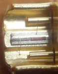
spot the problem :P
 

Attachments

  • broken_laser_die.JPG
    broken_laser_die.JPG
    164.3 KB · Views: 286
for future reference. DON'T extract open can diodes by pushing on the front of the diode.
although i have no idea how you are supposed to do it...
 
hah that's exactly what I was afraid of. when you pushed the diode out, the pliers must have contacted the die, or bent it. the 5V makes a lot more sense now, doesn't it
 
I can't focus that good, but I guess you're indicating a wire that is no longer connected to the input lead through the can. If thats the case, do you think excessive heat on the soldering iron caused it?

SN
 
SuperNova said:
I can't focus that good, but I guess you're indicating a wire that is no longer connected to the input lead through the can. If thats the case, do you think excessive heat on the soldering iron caused it?

SN

you can't see it?
let me help you out
 

Attachments

  • broken_laser_die1.JPG
    broken_laser_die1.JPG
    51.8 KB · Views: 443
drlava said:
hah that's exactly what I was afraid of. when you pushed the diode out, the pliers must have contacted the die, or bent it. the 5V makes a lot more sense now, doesn't it

i didn't actually touch the die, or anywhere around it. i used the pliers on the side bits of the front of the diode. it must have bent the whole base of the diode enough to snap the die in 3!
 
Thanks for the clarification.

If your interested, I could machine a die that mates to the form of that can. I bet jay could do the same. I have made my own die to adjust the focus inside the dx 70 and such that are buried in the heatsink. With the thread sealer used (loctite of sorts) using a needle nose is just not gonna cut it usually. I hate it when a focus ring is locked via sealant and "preset" but yeah no reason why you cant cough up a dead diode and have a "tool" made to fit it's edges and center to allow for simple extraction via a vise, die and tube plan.

If the die fits right, its simply a "push it out" deal

SN
 
I was thinking about something along those lines for extraction.
maybe a section of an extendable antenna would do the job

btw of anyone is interested, to take that photo i just got a jewlers magnifying glass and held it in front of my camera's lens
 
woop said:
I was thinking about something along those lines for extraction.
maybe a section of an extendable antenna would do the job

btw of anyone is interested, to take that photo i just got a jewlers magnifying glass and held it in front of my camera's lens

I was wondering and was going to ask, but you beat me to it. Great photo! What's the magnification on the loupe?
 
I got 2 comments

1 The closed can if encapsulated in a tight fit over the entire LD would utilize a heatsink as good or better then an open can that has no airflow.

2 Opening a can may allow better cooling if someone flows air over it or can make a heatsink touch the center (main source of heat dispersion)

Basically any diode needs air or conductive material touching it to dissipate the heat.

I would suggest buying a brass punch set and using a lathe (hand drill) to "turn it" to the diameter needed with a sand cloth and then machining (using a file) to create the indentations / depth of "non-needed" material to create such a tool to ease the removal process. Yeah a tube is needed for the part to fall into upon pushing it out, but more important is the "pushing" in the right places.

PM me if you want more advice, but basically,,, the idea is to push the part with a "die" (made to meet the wanted part on the right places) and a vise and tube to allow the part to "pass thru" without getting smushed on any given side. (like how a plier cant remain centered or a single point punch only contacts 1 point at a time)

SN
 
chimo said:
I was wondering and was going to ask, but you beat me to it. Great photo! What's the magnification on the loupe?
thats what its called, couldn't think of the name. its 18mm, 10x magnification

how where you taking macro shots of the blueray diode?


Back
Top