
Welcome to Laser Pointer Forums - discuss green laser pointers, blue laser pointers, and all types of lasers
How to Register on LPF | LPF Donations
Navigation
Install the app
How to install the app on iOS
Follow along with the video below to see how to install our site as a web app on your home screen.
Note: This feature may not be available in some browsers.
More options

You are using an out of date browser. It may not display this or other websites correctly.
You should upgrade or use an alternative browser.
You should upgrade or use an alternative browser.
Custom "El Cheapo" RGB Laser With FX Controller!
- Thread starter FishBulb32
- Start date


- Joined
- Jan 9, 2018
- Messages
- 32
- Points
- 18
Great to hear! I can’t wait to hear your thoughts on this. Some of the FX are impossible to explain and show to people on camera. There’s one that strobes between all the colours of the rainbow super fast and looks white when it’s still. Wave that around a wall, it’s very fun!Yeah I didn't bridge the mosfets. Thanks guys!
Maybe some photos too if you can.
Do you plan to house it in anything?
Also, I have since found a battery solution for mine. I took advantage of USB Power Delivery to force a power bank to give out 12v over USB C.
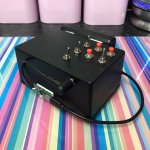
Last edited:
Away from home at the moment so i cant take any pictures yet but definitely excited to get this working, when you say bridging the mosfets do you mean just running 3 lines of solder across the back to bridge those connections on each of them or something else?
- Joined
- Jan 9, 2018
- Messages
- 32
- Points
- 18
Correct. Just flow the solder nicely so each hole is connected together. Imagine the line of solder completing the circuit instead of the MOSFET. To be clear, this is for each MOSFET, keeping the 3 channels separate.Away from home at the moment so i cant take any pictures yet but definitely excited to get this working, when you say bridging the mosfets do you mean just running 3 lines of solder across the back to bridge those connections on each of them or something else?
Good luck with it!
EDIT: I will try to get you a photo to make it clear.
EDIT:
Here you go. Just the top two. Leave leave them separate from the bottom pins. Hope this helps.
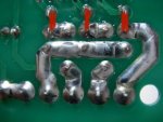
Last edited:
Thanks for the help so far!
Just got around to soldering those connections and it still won't work the module powers up white and the controller board has the LED come on but still wont respond to any input. While my soldering skills are pretty poor (as can be seen in the photos) nothing is unintentionally bridged, everything was installed according to the instructions, and I don't believe that I damaged any components.
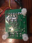
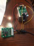
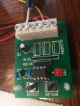
Just got around to soldering those connections and it still won't work the module powers up white and the controller board has the LED come on but still wont respond to any input. While my soldering skills are pretty poor (as can be seen in the photos) nothing is unintentionally bridged, everything was installed according to the instructions, and I don't believe that I damaged any components.


- Joined
- Jan 9, 2018
- Messages
- 32
- Points
- 18
I would probably separate the two modules at this point and see if we can diagnose them separately.
I trust you have no issues changing the colour of the laser just by shorting each TTL pin on the laser board? Power the laser on its own. Shorting the red pins together for example will turn off the red channel leaving green and blue on. If this is ok then the issue is with the FX controller. This is more likely.
With my controller I knew it was working from when I used it with LEDs. So I can’t say I’ve spent any real time diagnosing it. But you should be getting a voltage out the end of each of the colours. Do you have a multi meter to check?Keep in mind that the unit could be changing modes so you might get a period of “off” so check for a longer time and try changing the mode incase the mode it is on doesn’t need the colour you are testing.
If you’re not getting a voltage then there must be an issue with the controller somewhere.
- Joined
- Jan 9, 2018
- Messages
- 32
- Points
- 18
That’s a relief! Glad it’s nothing serious. I was trying to figure out how it was wired. Was hard to see from the photos.
Keep me updated! Have fun!
Keep me updated! Have fun!
- Joined
- Jul 20, 2011
- Messages
- 6
- Points
- 1
This is very cool. Unfortunately, I have to buy one now. 

