

names TJ
0
- Joined
- Mar 4, 2015
- Messages
- 9
- Points
- 0
I have a few adjustable drivers which are the round type with the bottom doubling as the contact board. I wanted to hear, or if you have pics then see, what ideas you guys are using to temporarily connect your power source to the contact board for setting the amperage on the drivers with a test load before connecting the diodes. Obviously we can simply solder temporary wires to the bottom with a dab of solder or install the driver in a host but there are some pretty clever people on this site so I figured I would see what methods you fine gentlemen are using.
Ready, set...go!
Ready, set...go!


 Total rookie mistake, I know. Live and learn lol
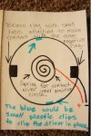
")