Bluefan
0
- Joined
- Aug 15, 2009
- Messages
- 1,443
- Points
- 48
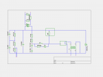
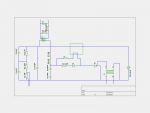
I have a yag laser from a range finder, but the electronics are quite a mystery. It was way to complicated to work out completely, so I tried to figure out the pfn, pretty all I need for a start. The active q-switch circuit is glued in a case, so I won't be getting that one out soon, but first I want to have a flash. I included the circuit diagram as far as I could figure it out.
There are 4 wires sticking out, I can trace them futher into another pcb, but I think that would be the control, not the pfn. All I've drawn here is from a single pcb and the storage cap.
On the left top part of the circuit I've drawn the two coils (L1 and L2) close to eachother, these are stacked op top of eachother and probably interacting. The thing I've drawn as a fuse is a small glass component I couldn't easily measure what it was.
The inductor L3 is a coil sitting below a similar round shaped part of the first large unknown component drawn by the box.
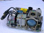
There are 2 boxes drawn. The big one on the top connects the high voltage of the storage cap directly to the flashlamp with some fat wires and with an internal resistor to another part. The box is a single large part of the pfn which I only can measure the resistance. I can't measure inductance with my meter, so the direct connection may have a inductance.
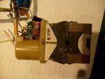
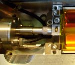
The second one is a small part, a small metal can connected to the circuit and on the other end two connections. I have no idea what it, but I measures a practically direct connection between two pins and nothing to the other pin. I included a photo of the object.
The transformer is actually a very small black box on the pcb, I think to seperate the circuit from the control logic. I think it is used to trigger the circuit somehow, but the circuit doesn't make sense to me.
Anyone any idea how it should work? I've drawn thing with an upside, but I don't even know the polarity of the circuit, so crude testing may be dangerous.
The attachments:
- circuit diagram
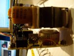
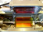
- foto from side of electronics
- closeup of second "box" component with in front the small transformer
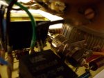
- the big "box" component with L1 and L2 visible
I you want a high-res picture of the circuit diagram, look at images.bluefan.nl/circuit_yag.png
There are 4 wires sticking out, I can trace them futher into another pcb, but I think that would be the control, not the pfn. All I've drawn here is from a single pcb and the storage cap.
On the left top part of the circuit I've drawn the two coils (L1 and L2) close to eachother, these are stacked op top of eachother and probably interacting. The thing I've drawn as a fuse is a small glass component I couldn't easily measure what it was.
The inductor L3 is a coil sitting below a similar round shaped part of the first large unknown component drawn by the box.
There are 2 boxes drawn. The big one on the top connects the high voltage of the storage cap directly to the flashlamp with some fat wires and with an internal resistor to another part. The box is a single large part of the pfn which I only can measure the resistance. I can't measure inductance with my meter, so the direct connection may have a inductance.
The second one is a small part, a small metal can connected to the circuit and on the other end two connections. I have no idea what it, but I measures a practically direct connection between two pins and nothing to the other pin. I included a photo of the object.
The transformer is actually a very small black box on the pcb, I think to seperate the circuit from the control logic. I think it is used to trigger the circuit somehow, but the circuit doesn't make sense to me.
Anyone any idea how it should work? I've drawn thing with an upside, but I don't even know the polarity of the circuit, so crude testing may be dangerous.
The attachments:
- circuit diagram
- foto from side of electronics
- closeup of second "box" component with in front the small transformer
- the big "box" component with L1 and L2 visible
I you want a high-res picture of the circuit diagram, look at images.bluefan.nl/circuit_yag.png