Welcome to Laser Pointer Forums - discuss green laser pointers, blue laser pointers, and all types of lasers

LPF Donation via Stripe | LPF Donation - Other Methods

Links below open in new window

ArcticMyst Security by Avery

Triple Switchable Output, Lab Style PL520 Build w/Custom Linear Power Supply

Joined
Jun 20, 2015
Messages
249
Points
43
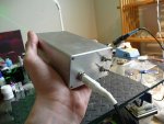
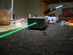
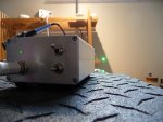
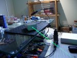
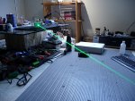
Just thought I'd share this PL520 build I did a few months back to add something to the sound of tumble weeds rolling through the lands of LPF builds lately :)

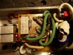
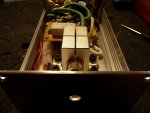
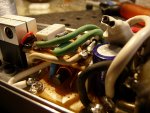
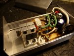
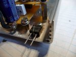
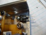
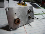
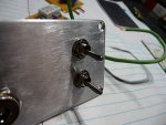
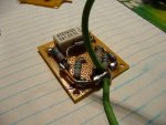
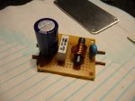
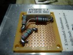
I wanted switchable output with the lowest output having some degree of eye safety (keeping in mind something should never actually be considered "eye safe" from any laser) so I gave it outputs of <5mw, ~40mw and ~110mw in a switching network I designed using a double pole switch that controls the output by changing between program resistors with the off position being the lowest setting, the other two positions adding parallel resistance (so, technically less resistance...higher current) on top of the base resistor set. Linear regulator is the LM317 with ripple smoothing, spike filtering and full bypass caps Eight Ways to Sunday. I found the G7 had a nice clean output and stuck with it, also tried the acrylic which looked good as well but the output fell noticeably and the 3 element just looked dirty (bad dirty).

Speaking of dirty, I couldn't stop laughing after looking at the picture of the LM317 mounted to the case before I soldered it. Seriously didn't end up like that on purpose.

Here's the pics...
 

Attachments

  • Image00002.jpg
    Image00002.jpg
    597.6 KB · Views: 81
  • Image00003.jpg
    Image00003.jpg
    424.8 KB · Views: 90
  • Image00004.jpg
    Image00004.jpg
    649.2 KB · Views: 115
  • Image00005.jpg
    Image00005.jpg
    616.9 KB · Views: 78
  • Image00006.jpg
    Image00006.jpg
    448.4 KB · Views: 65
  • Image00007.jpg
    Image00007.jpg
    652.8 KB · Views: 104
  • Image00001.jpg
    Image00001.jpg
    683.9 KB · Views: 105
Last edited:


Joined
Jun 20, 2015
Messages
249
Points
43
That sunbathing LM317...
 

Attachments

  • Image00022.jpg
    Image00022.jpg
    695.1 KB · Views: 105
  • Image00019.jpg
    Image00019.jpg
    568.5 KB · Views: 79
  • Image00011.jpg
    Image00011.jpg
    586.9 KB · Views: 87
  • Image00024.jpg
    Image00024.jpg
    518.1 KB · Views: 81
  • Image00023.jpg
    Image00023.jpg
    640.4 KB · Views: 75
  • Image00020.jpg
    Image00020.jpg
    687.9 KB · Views: 68
  • Image00010.jpg
    Image00010.jpg
    619.9 KB · Views: 95
  • Image00008.jpg
    Image00008.jpg
    607.4 KB · Views: 92
Joined
Jun 20, 2015
Messages
249
Points
43
...and the rest of the pics of it finished in my eh, shop. I'm happy with the way the micro led power indicator turned out, simply drilled a hole and slapped on the backside.
 

Attachments

  • Image00013.jpg
    Image00013.jpg
    588 KB · Views: 67
  • Image00014.jpg
    Image00014.jpg
    592.1 KB · Views: 59
  • Image00015.jpg
    Image00015.jpg
    591.9 KB · Views: 68
  • Image00016.jpg
    Image00016.jpg
    636.6 KB · Views: 55
  • Image00017.jpg
    Image00017.jpg
    678.4 KB · Views: 69
  • Image00018.jpg
    Image00018.jpg
    721.7 KB · Views: 70
Last edited:
Joined
Mar 5, 2015
Messages
1,336
Points
113
Nice job, very nice,
Yeah not many builds being posted lately, hopefully I'll have something to show-contribute tomorrow!
 

BobMc

0
Joined
Apr 23, 2016
Messages
3,685
Points
113
Badboy with a new build thread. My hearts starting to beat faster. :D
 
Joined
Sep 20, 2013
Messages
17,454
Points
113
Interesting. I haven't seen this kind of build using an LM317 like this before now. I see you prefer using proto-boards over printing circuit boards. That is fine for one of a kind builds like this. +rep.
 
Joined
Sep 12, 2007
Messages
9,399
Points
113
Physically switching the sense resistors is a ballsy move, man. You have no feedback for several milliseconds; caps or not, this is gonna cause some spikes.
 
  • Like
Reactions: GSS

Benm

0
Joined
Aug 16, 2007
Messages
7,896
Points
113
Switching is not going to be that much of a problem really, the switches go open circuit between positions so there should only be power drops, not spikes.

The thing i dislike about it is mounting the lm317 electrically connected to the enclosure: the middle pin and tab of an lm317 are connected to it's output. The unit may still work, but i really prefer to have the case either isolated completly or connected to ground. If you put this on top of somthing that has it's case connected to ground it would short out the output. In this case it'd probably just turn the laser off and make the lm317 go into self-preservation shutdown, but it's not a good idea to begin with.
 
Joined
Jun 20, 2015
Messages
249
Points
43
The thing i dislike about it is mounting the lm317 electrically connected to the enclosure: the middle pin and tab of an lm317 are connected to it's output. The unit may still work, but i really prefer to have the case either isolated completly or connected to ground.

The LM317 is insulated from the case, you can see the mica wafer in the picture of the regulator... the screw is also going through a teflon shield and washer isolating the securing side of the metal tab.
 

Benm

0
Joined
Aug 16, 2007
Messages
7,896
Points
113
Ah, in that case no problem at all. I figured it was just some heatsinking pad you used there as the bolt is metal.

I know of the insulating washer being available, but i prefer to use nylon bolts and nuts when mouting things electrically insulated. It's not required by any means but more easily to identify as electrically insulated of anyone attemps to do further work on the circuit. I figure it cannot get hot enough for the nylon to be a problem given the internal thermal limiting in the lm317.


Top